This assumes you are using ufw. ufw is bascally a wrapper for IPTABLES. If you have ever used IPTABLES before you understand why ufw exists. Replace port_number with the real port number
1 2 3 4
sudo ufw default allow routed sudo ufw allow from A.B.C.0/24 to any port port_number proto tcp sudo ufw allow from D.E.F.0/24 to any port port_number proto tcp sudo ufw status
Error from server (BadRequest): container in pod is waiting to start: ContainerCreating You probably need to change the permissions on the PV directory. This path is what is written in the PersistentVolume in the path variable. A quick chmod -R 777 to this path will most likely fix the issue. The conatiner should update the permissions once it runs.
Service yaml file
Since we are using the hostnetwork we don’t need the an additional service file to route information.
This assumes you are using ufw. ufw is bascally a wrapper for IPTABLES. If you have ever used IPTABLES before you understand why ufw exists. https://docs.syncthing.net/users/firewall.html
1
sudo ufw default allow routed
1 2 3
sudo ufw allow from A.B.C.0/24 to any port WEB_GUI_PORT proto tcp sudo ufw allow from A.B.C.0/24 to any port AUTO_DISCOVER_PORT proto udp sudo ufw allow from A.B.C.0/24 to any port DLNA_PORT proto udp
Modify the values.yaml file to set the configuration
1 2 3
tar -xvf ./zigbee2mqtt-*.tgz cd zigbee2mqtt cat values.yamls
1 2 3 4 5 6
EXTERNAL_IP: A.B.C.D EXTERNAL_NETWORK: A.B.C.0 SERVICE_PORT: Port used by the application ZIGBEE_ADAPTER_IP: Ip address of the zigbee adapter ZIGBEE_ZIGBEE_ADAPTER_PORT: Port used by the external zigbee adapter MQTT_PORT: PORT_C
Create Persistent Volumes and Persistent Volume Claims
Transmission can think you deleted all your files if the harddisk containing your files fails to mount and the configuration files are on a different disk.
Error from server (BadRequest): container in pod is waiting to start: ContainerCreating You probably need to change the permissions on the PV directory. This path is what is written in the PersistentVolume in the path variable. A quick chmod -R 777 to this path will most likely fix the issue. The conatiner should update the permissions once it runs.
Service yaml file
We need to expose the service to the outside world. Thankfully microk8s has a built in loadbalancer called metallb
WEBGUI_PORT_NUMBER: The port you wish to run the webgui on TRANSMISSION_PORT: The port Transmission uses to comminicate with external parties.
microk8s kubectl get services transmission-service
1
2
NAME TYPE CLUSTER-IP EXTERNAL-IP PORT(S) AGE transmission-service LoadBalancer A.B.C.D X.Y.Z.A TRANSMISSION_PORT:TRANSMISSION_PORT_2/TCP,TRANSMISSION_PORT:TRANSMISSION_PORT_2 /UDP,WEBGUI_PORT_NUMBER:31056/TCP 9h
Firewall Rules
This assumes you are using ufw. ufw is bascally a wrapper for IPTABLES. If you have ever used IPTABLES before you understand why ufw exists. https://docs.syncthing.net/users/firewall.html
1 2 3 4 5 6 7 8
sudo ufw default allow routed
sudo ufw allow from A.B.C.0/24 to any port WEBGUI_PORT_NUMBER proto tcp sudo ufw allow from E.F.G.H/24 to any port TRANSMISSION_PORT proto tcp sudo ufw allow from E.F.G.H/24 to any port TRANSMISSION_PORT proto udp
Modify the values.yaml file to set the configuration
We’re going to set the syncthing configuration within the container.
1 2 3
tar -xvf ./syncthing-15.0.1.tgz cd syncting cat values.yamls
Make the data directory
1 2 3 4 5
mkdir /path/to/ chown -R 777 /path/to/
mkdir /path/to/data chown -R 777 /path/to//data
Create Persistent Volumes and Persistent Volume Claims
If the Syncthing configuration files are on a different disk than your files and the harddisk containing your files fails to mount, Syncthing can think you deleted all your files. Syncthing will then tell the other nodes to delete all files in that directory. To prevent this issue, we will store the configuration along with the files. If the harddisk does not mount the entire node will disappear and will not corrupt any other Syncthing nodes.
Error from server (BadRequest): container in pod is waiting to start: ContainerCreating
You probably need to change the permissions on the PV directory. This path is what is written in the PersistentVolume variable. A quick chmod -R 777 to this path will most likely fix the issue. The conatiner should update the permissions once it runs for the first time.
Service yaml file
We need to expose the service to the outside world. Thankfully microk8s has a built in loadbalancer called metallb
PORTA TCP – Webserver/HTTP PORTB TCP/UDP – TCP - TCP based sync protocol traffic, UDP - QUIC based sync protocol traffic PORTC UDP – for discovery broadcasts on IPv4 and multicasts on IPv6
This assumes you are using ufw. ufw is bascally a wrapper for IPTABLES. If you have ever used IPTABLES before you understand why ufw exists. https://docs.syncthing.net/users/firewall.html
1 2 3 4 5 6 7 8 9
sudo ufw default allow routed
sudo ufw allow from A.B.C.D/24 to any port PORTA proto tcp sudo ufw allow from 0.0.0.0/24 to any port PORTB proto tcp sudo ufw allow from 0.0.0.0/24 to any port PORTB proto udp sudo ufw allow from 0.0.0.0/24 to any port PORTC proto udp
apiVersion: v1 kind: PersistentVolume metadata: name: mosquitto-data-pv spec: capacity: storage: 3Ti volumeMode: Filesystem accessModes: - ReadWriteOnce persistentVolumeReclaimPolicy: Retain storageClassName: local-storage local: path: /path/to/files/mosquitto/data # This must exist on the host nodeAffinity: required: nodeSelectorTerms: - matchExpressions: - key: kubernetes.io/hostname operator: In values: - example_host
microk8s kubectl apply -f mosquitto-data-pv.yaml
1
persistentvolume/mosquitto-data-pv created
Verify PV
microk8s kubectl get pv
1 2 3
NAME CAPACITY ACCESS MODES RECLAIM POLICY STATUS CLAIM STORAGECLASS REASON AGE mosquitto-configinc-pv 3Ti RWO Retain Available local-storage 97s mosquitto-data-pv 3Ti RWO Retain Available local-storage 35s
Persistent Volume Claims
configinc
mosquitto-configinc-pvc.yaml
mosquitto-configinc-pvc.yaml Bonds to mosquitto-configinc-pv
1
2
3
4
5
6
7
8
9
10
11
12
apiVersion: v1
kind: PersistentVolumeClaim
metadata:
  name: mosquitto-configinc-pvc
spec:
  storageClassName: local-storage # Empty string must be explicitly set otherwise default StorageClass will be set
  accessModes:
    - ReadWriteOnce
  volumeName: mosquitto-configinc-pv
  resources:
    requests:
      storage: 3Ti
microk8s status
microk8s kubectl show pods
microk8s kubectl
microk8s kubectl logs
microk8s kubectl describe pods
Common Errors
Error from server (BadRequest): container in pod is waiting to start: ContainerCreating You probably need to change the permissions on the PV directory. This path is what is written in the PersistentVolume in the path varaibale. A quick chmod -R 777 to this path will most likely fix the issue. The conatiner should update the permissions once it runs.
Service yaml file
We need to expose the service to the outside world. Thankfully microk8s has a built in loadbalancer called metallb
Replace Y with the MQTT port number. Default 1883 Replace Z with the MQTT API number Default 9001
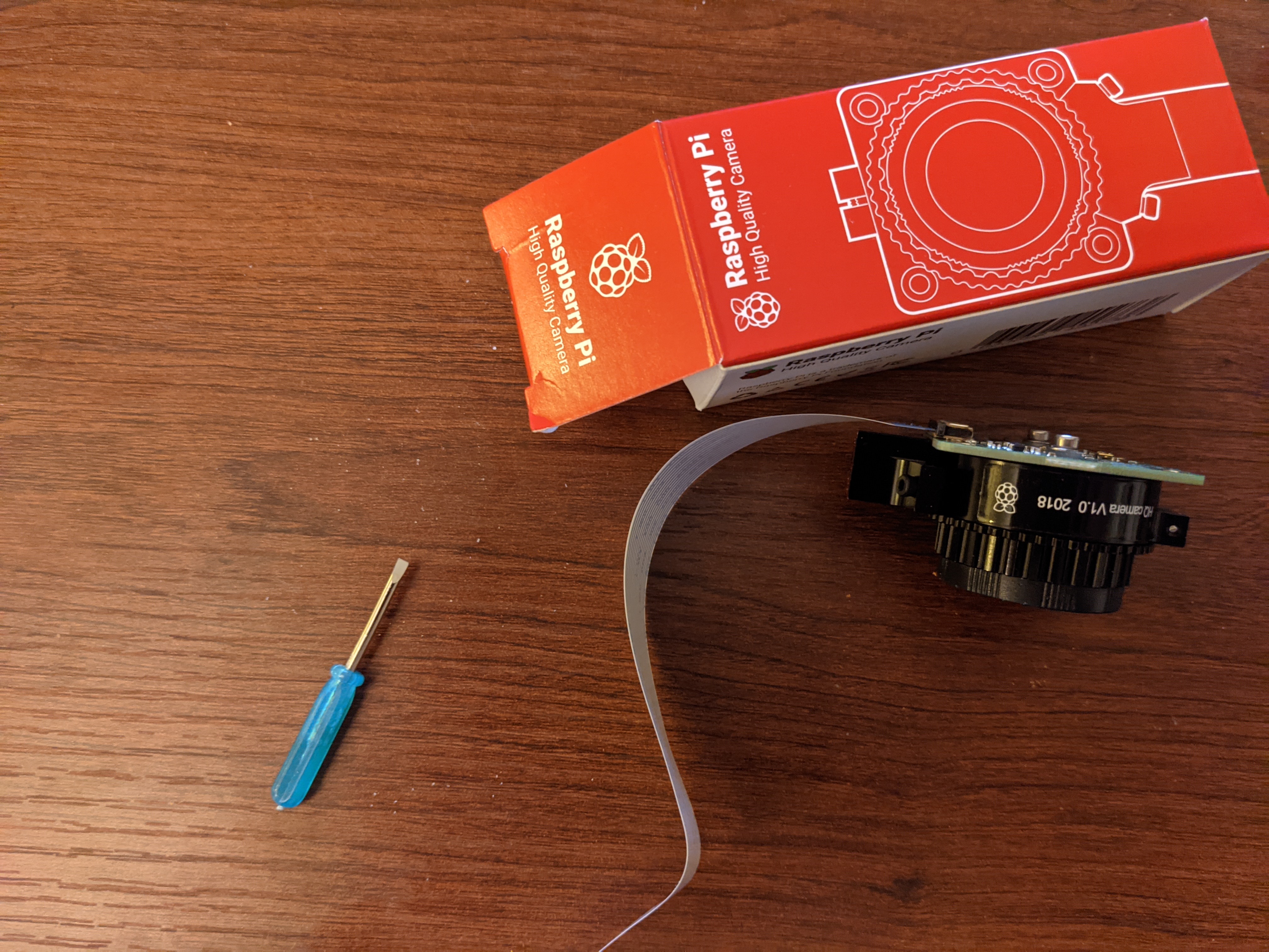
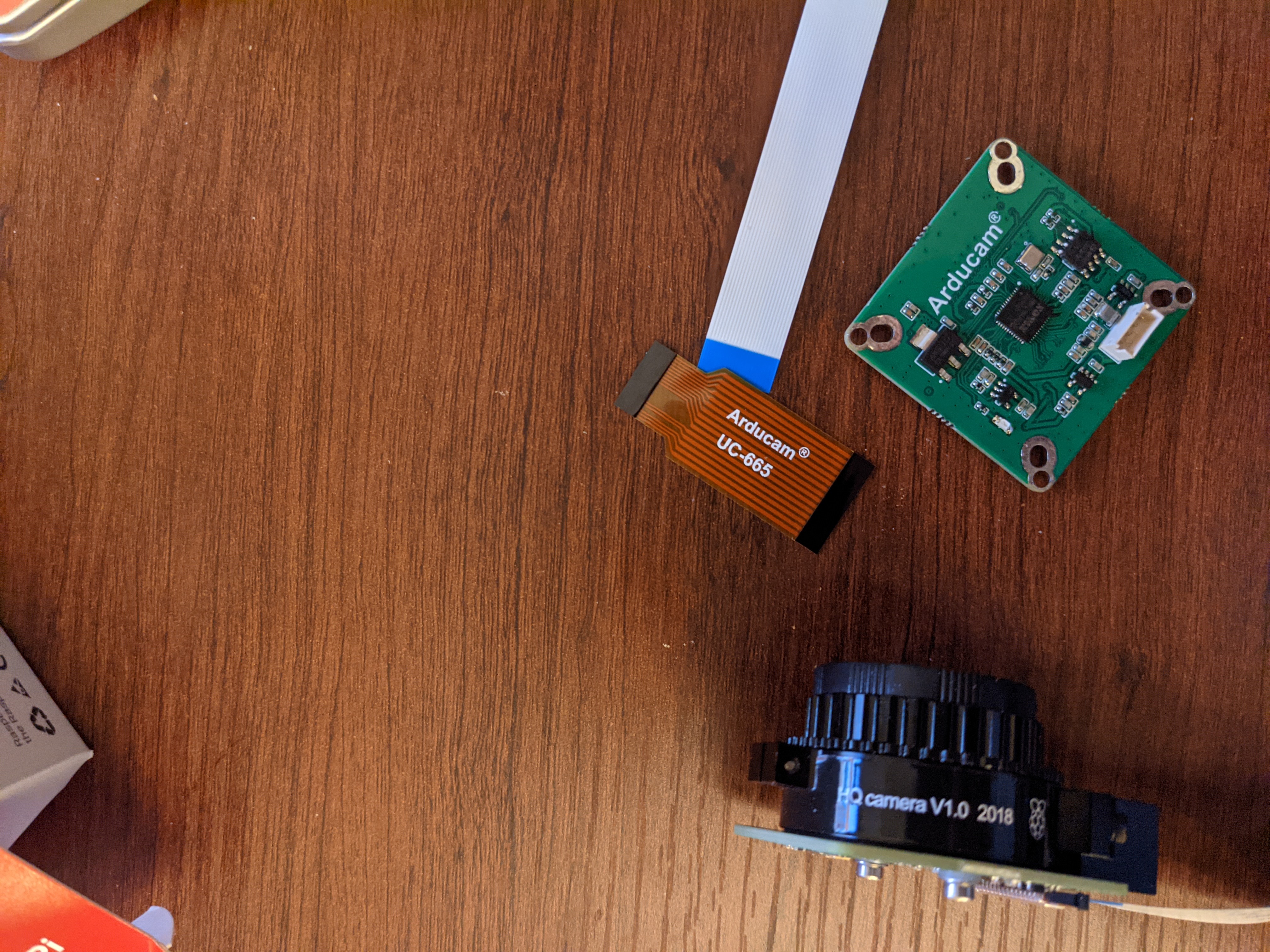
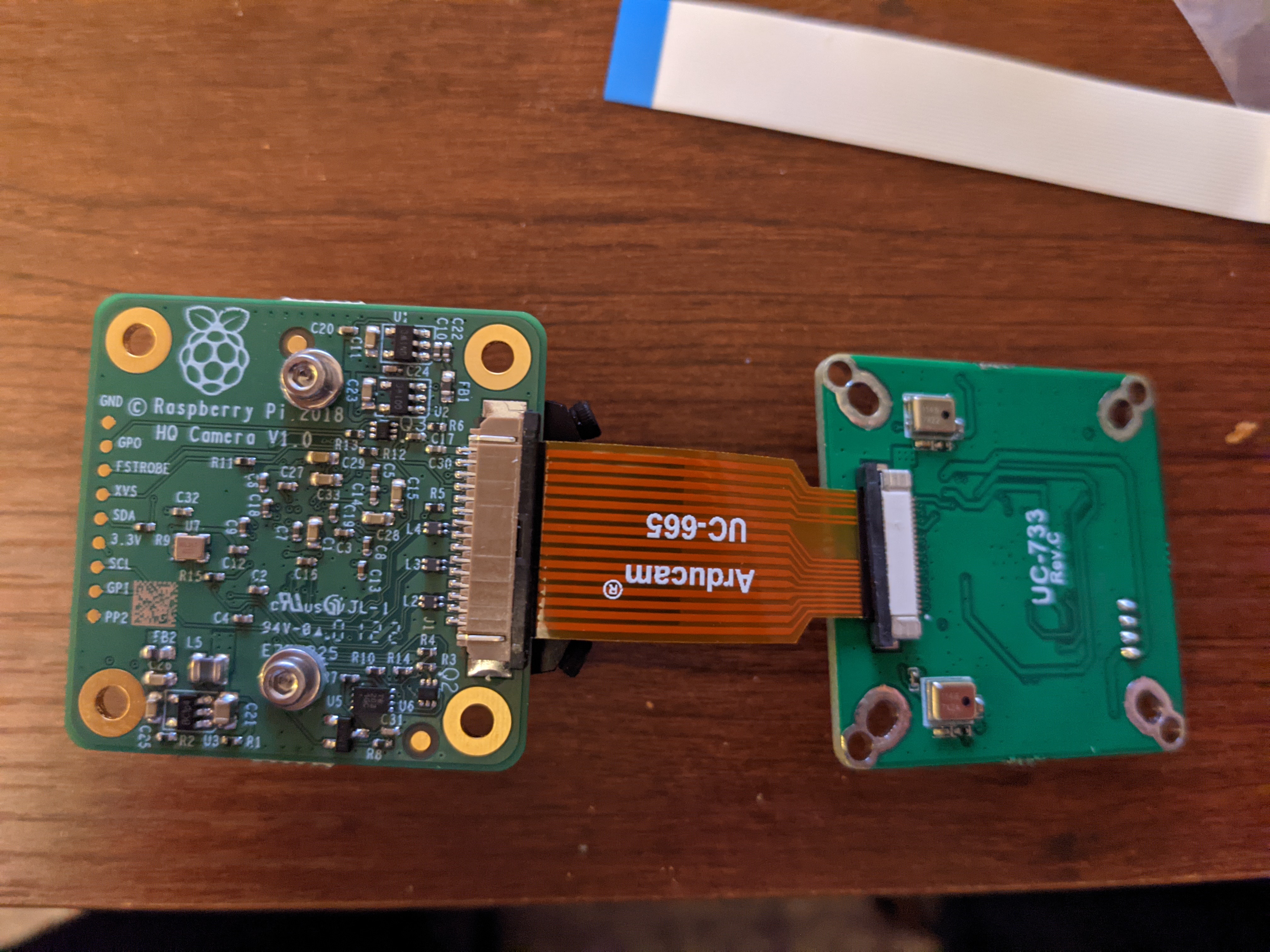
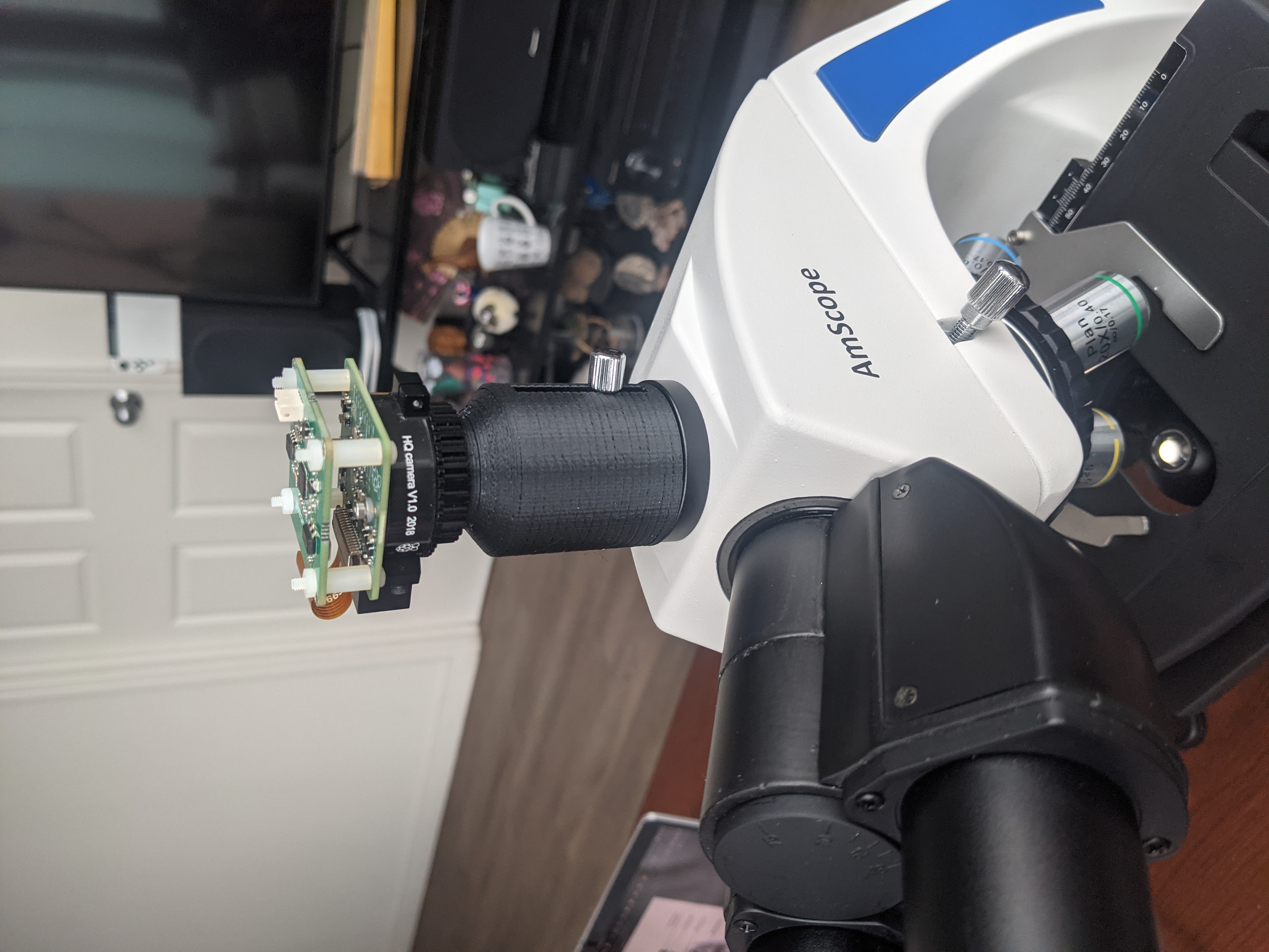
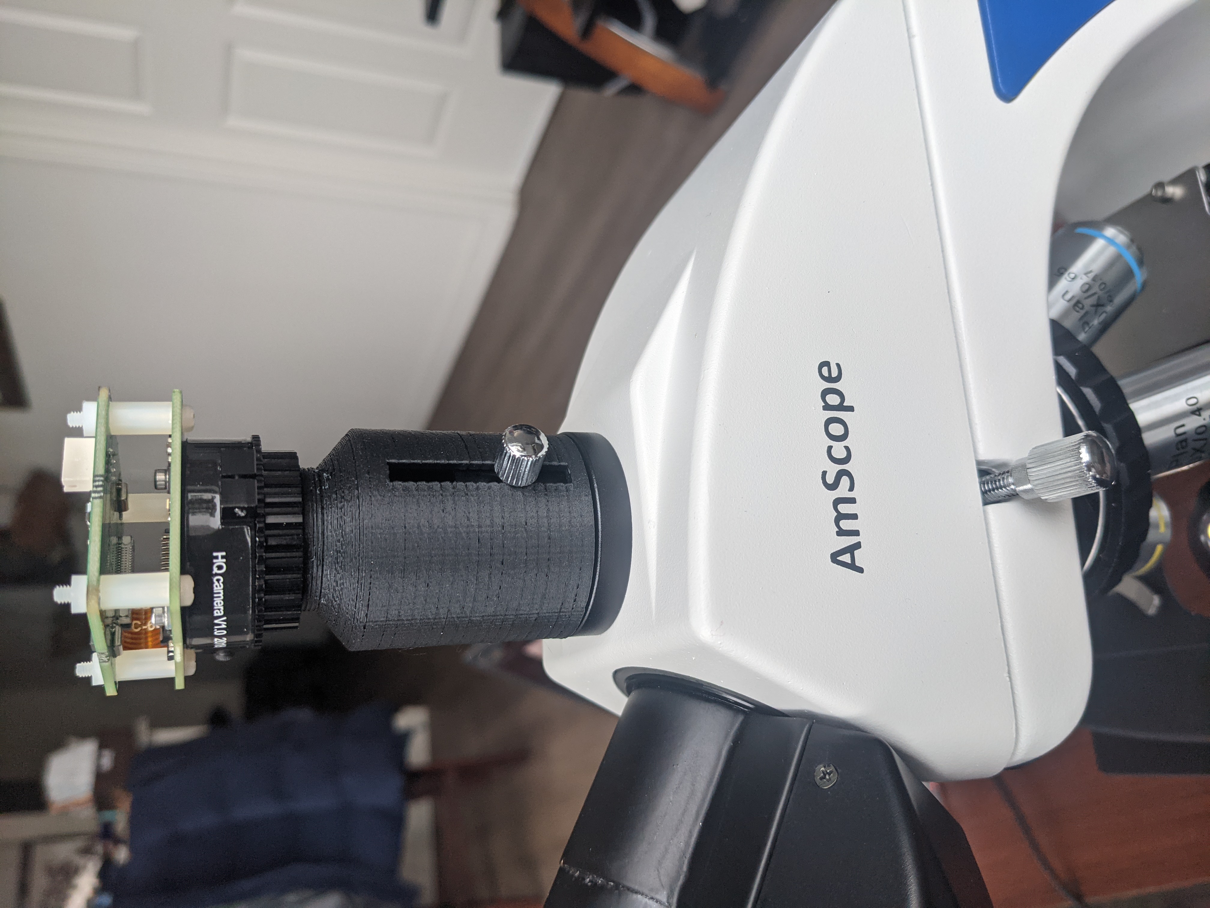
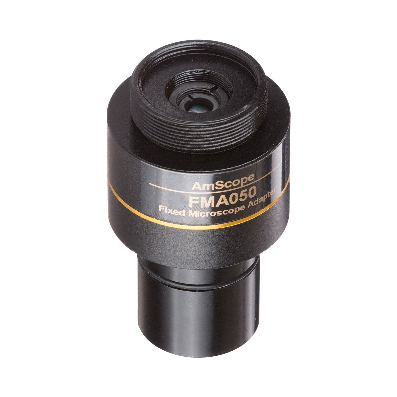
In order to correct for the inherent magnification effect an adapter was purchased. From these sources I was able to find that 0.3x to 0.5x is about correct for my sensor size
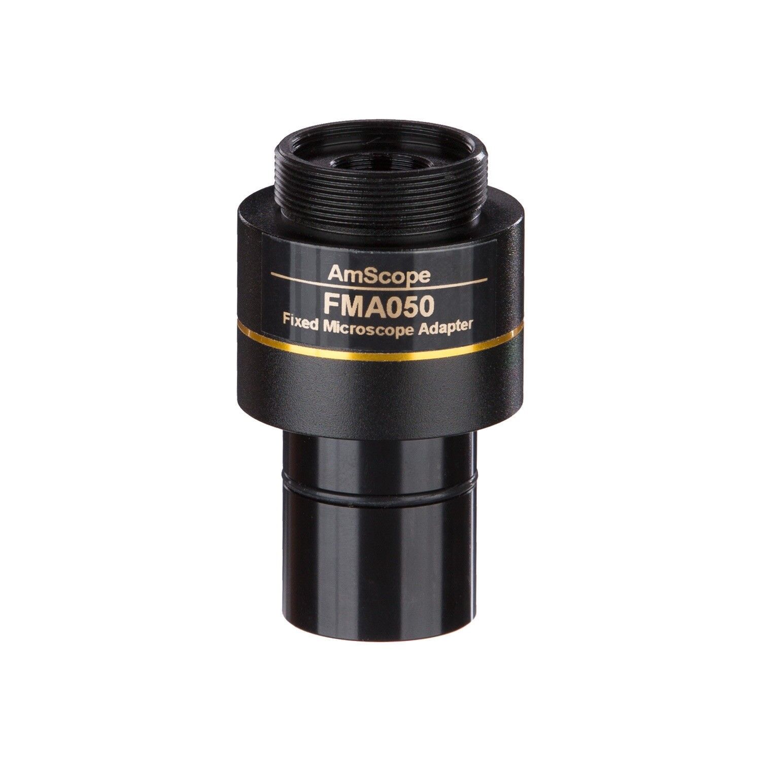
Adapter lens selection
AmScope RU050 0.5X Reduction Lens for C-mount Cameras FMA050 Cmount to 23mm adapter. This fits my AmScope T720B Scope
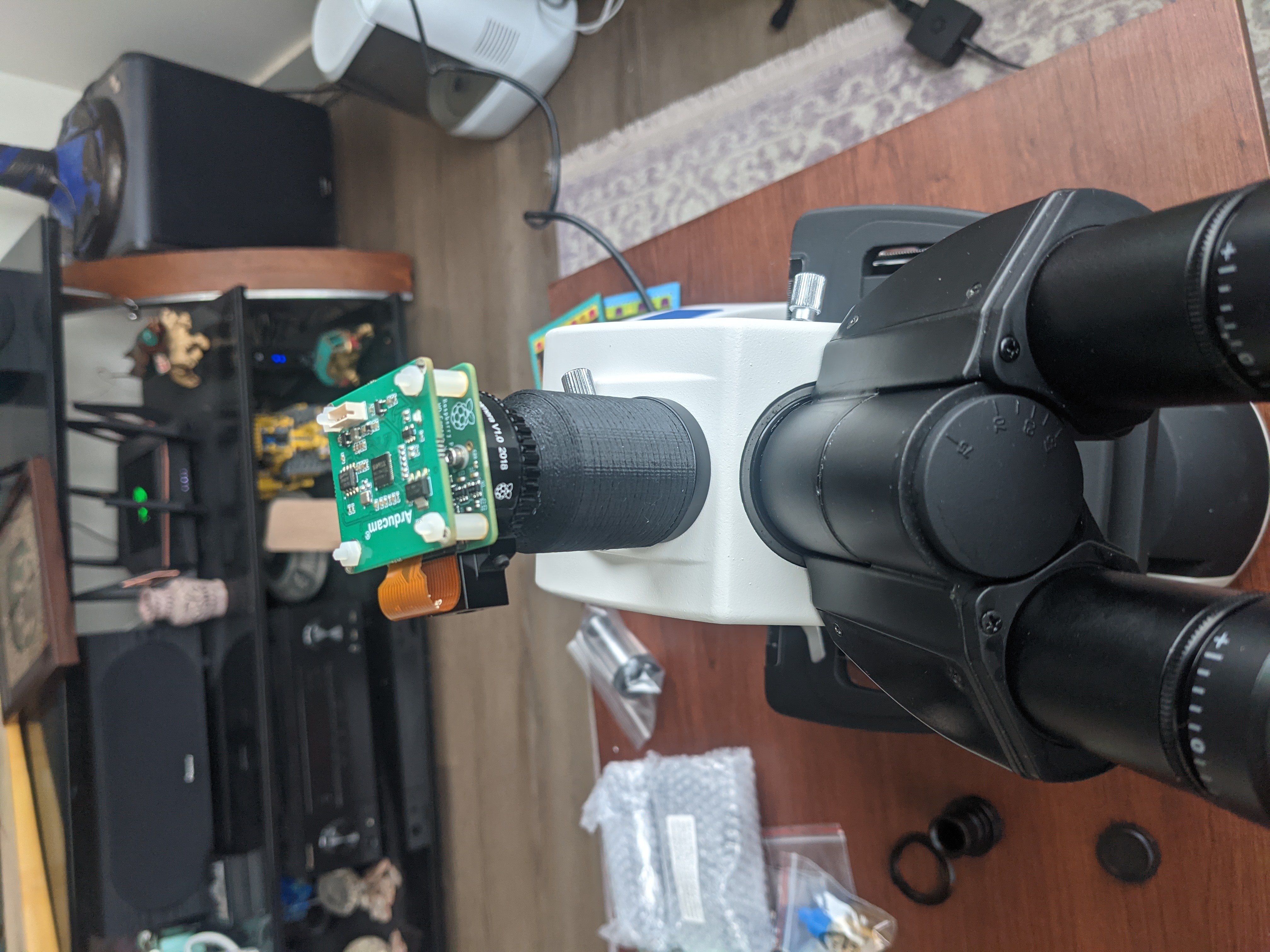
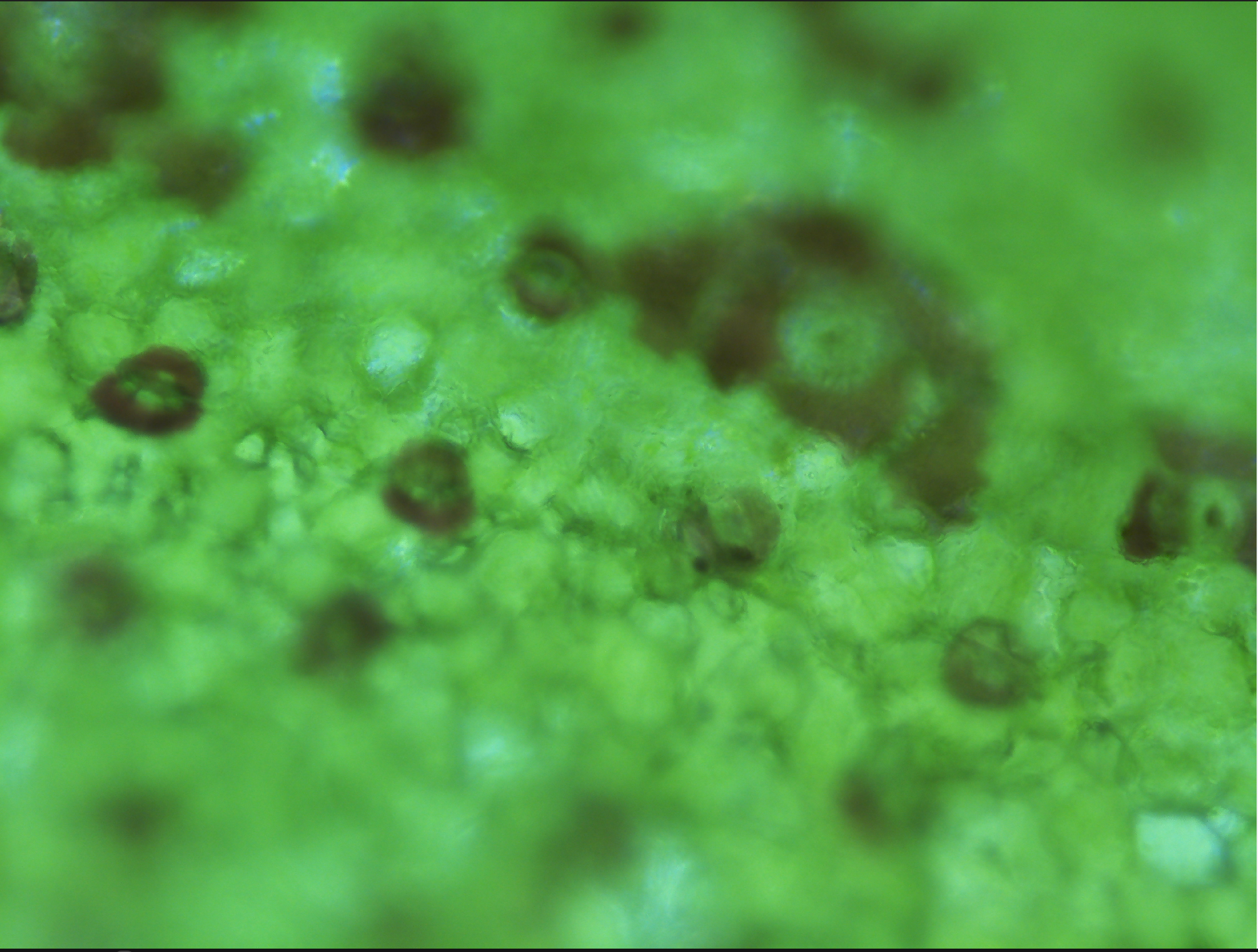
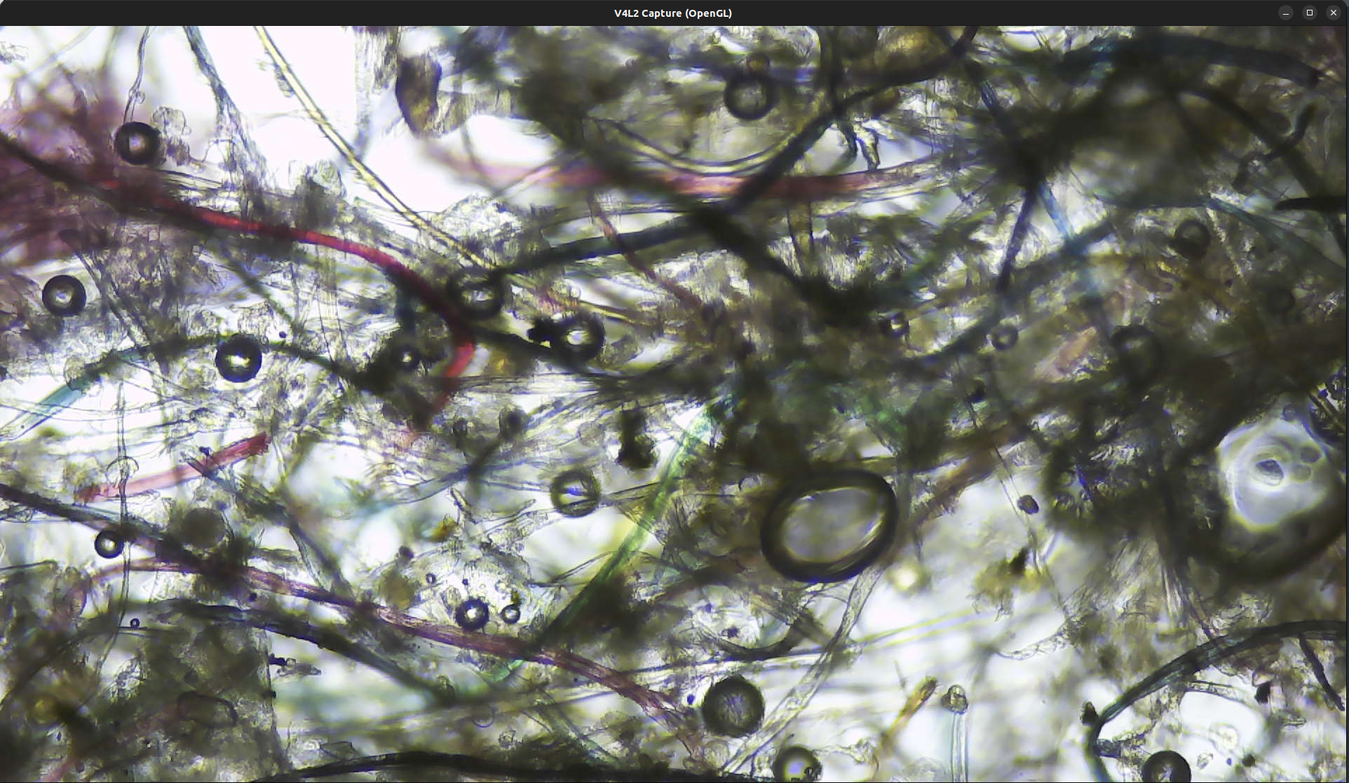
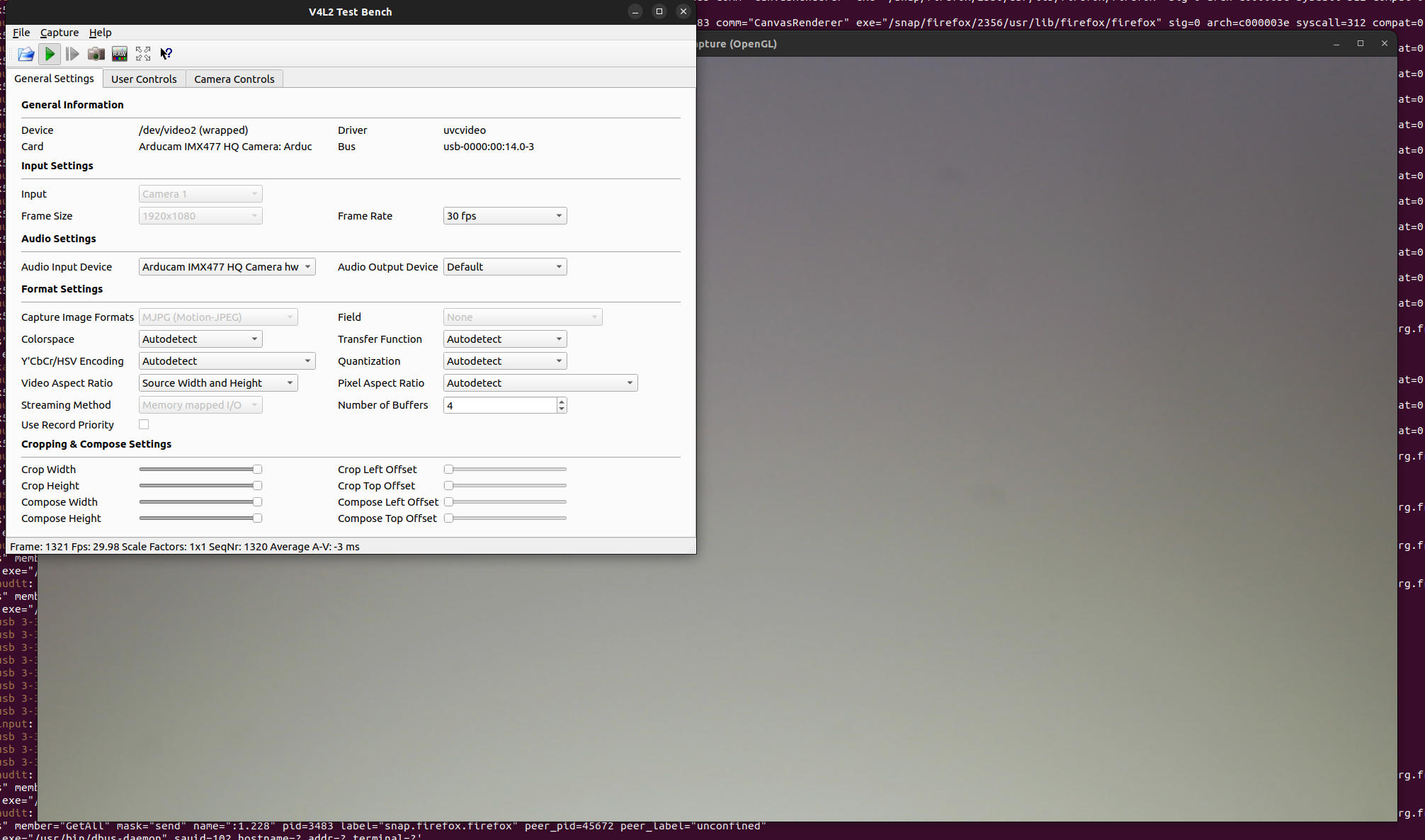
I had problems with Cheese constantly changing the exposure. Thankfully many have suffered from this issue before. I found this link that is specific to the raspberry pi but useful. https://hackernoon.com/polising-raspberry-pi-high-quality-camera-3z113u18 I had to use a more advanced pieace of software called qv4l2
Infinity Corrected Optical System with High Resolution Fully Coated Optics with Crystal Clear & Sharp Images Precise Mechanical Control System Reversed Nosepiece Design Kohler Illumination System with Field Diaphragm for Lighting Control 30-Degree Inclined, 360-Degree Swiveling, Compensation Free Trinocular Head Eight Magnification Levels: 40X, 80X, 100X, 200X, 400X, 800X, 1000X, 2000X Intensity-Variable Transmitted LED Lighting System Abbe Condenser with Iris Diaphragm and Filter Holder Rack and Pinion Adjustment for Condenser Low Position Coaxial Stage Movement Controlling Knobs Dual Side Coaxial Coarse and Fine Focusing Control Adjustable Interpupillary Distance Adjustable Diopter on Eyepieces Durable Cast Alloy Frame with Stain Resistant Enamel Finish Four Infinity Plan Objectives Included Two Pairs of Extreme Widefield Eyepieces Included (EWF10X & WF20X) Quadruple, Reversed, Extra-Large Nosepiece with Wide, Knurled Grip for Easy Operation Large Double Layer Mechanical Stage with Stain Resistant Coating Upward Stage Limit Stop to Protect Objectives and Slides Manufactured under ISO 9001 Quality Control Standards Excellent Five (5) Year Factory Warranty
Specifications : Optical System: infinity corrected Nosepiece: reversed, ball bearing quadruple Head: gemel type trinocular head, 30-degree inclined Eyepiece: high eye-point eyepieces, WF10X22mm, WF20X Objectives: infinity plan objective 4X, 10X, 40X (spring), 100X (spring, oil) Focusing: low position coaxial focus system Focusing Range: 1-3/16” (30mm) Interpupillary Adjustment Range: 2-3/16” - 3” (55-75mm) Mechanical Tube Length: 6-5/16” (160mm) Mechanical Stage: 8.5” x 5.9” (216mm x 150mm) Stage Traveling Range: 2.9” x 2” (75x50mm) Focusing Rang: 0.95” (24mm) Division of Fine Focusing: 0.00003935” (0.001mm) Illuminator: Built-in Kohler LED illumination system Condenser: N.A. 1.25 achromatic condenser Illumination: Kohler, LED Power Supply: 90V-240 wide voltage, CE certified Built in measurement capabilities Weight: 28 lbs
Packing List : One Trinocular Compensation-Free Head One Microscope Body with Frame, Base, and Kohler Illumination System Four High Quality DIN Plan Achromatic Objectives: 4X, 10X, 40X and 100X One Pair of Widefield Eyepieces: WF10X One Pair of Widefield Eyepieces: WF20X One Dust Cover One HDMI camera One HDMI cable Immersion Oil User’s Manual
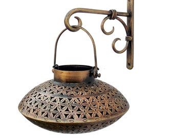
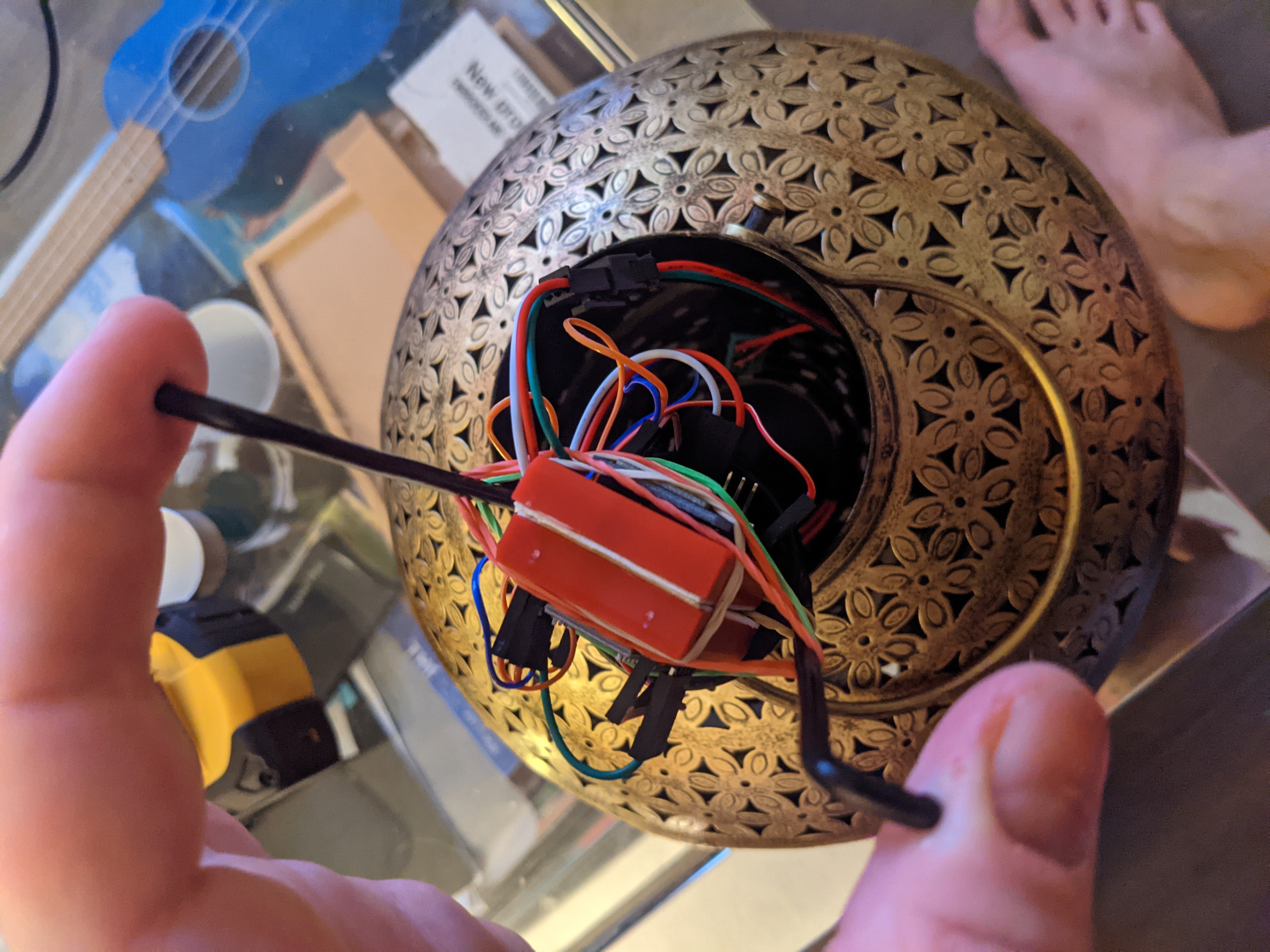
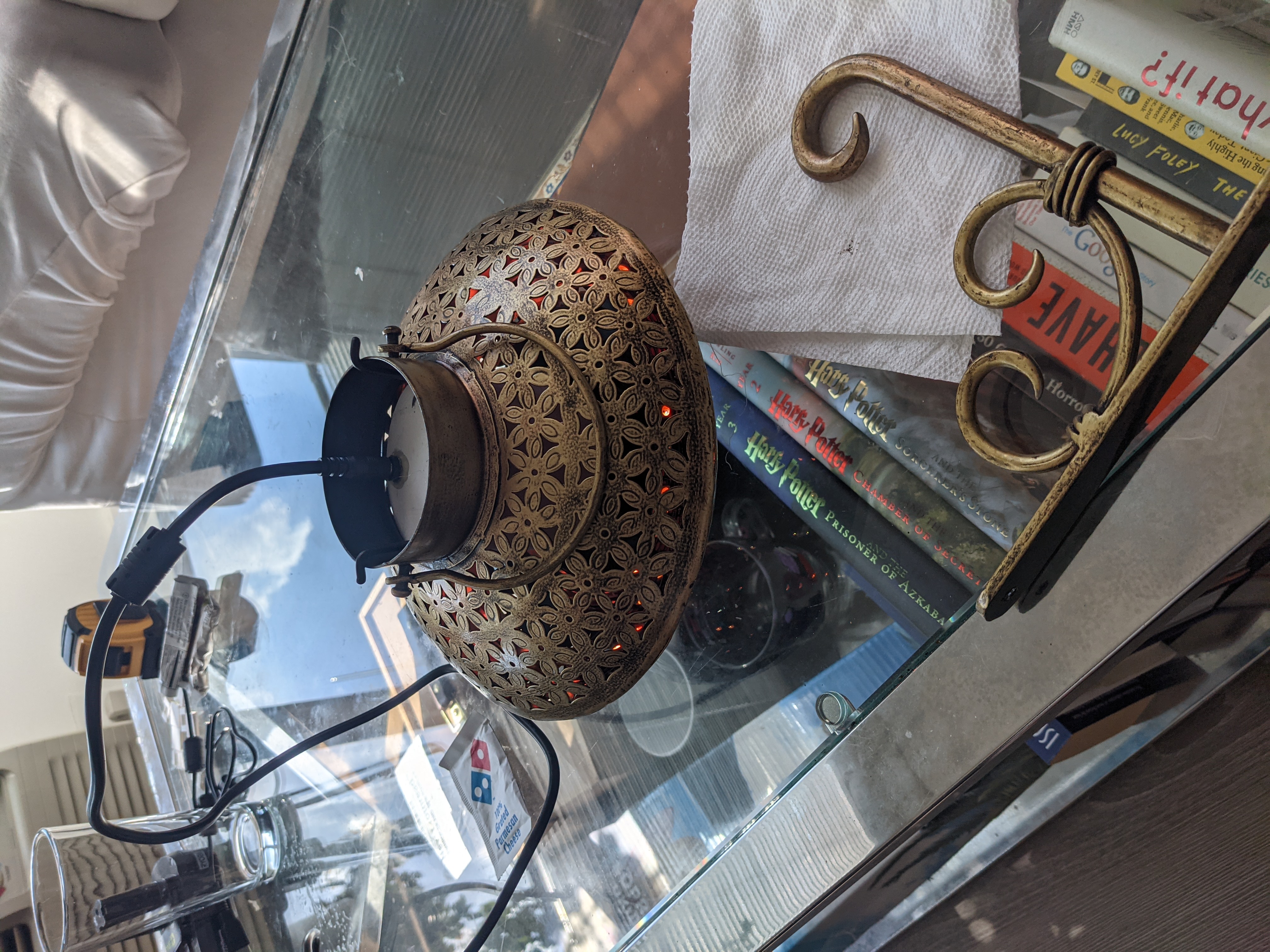
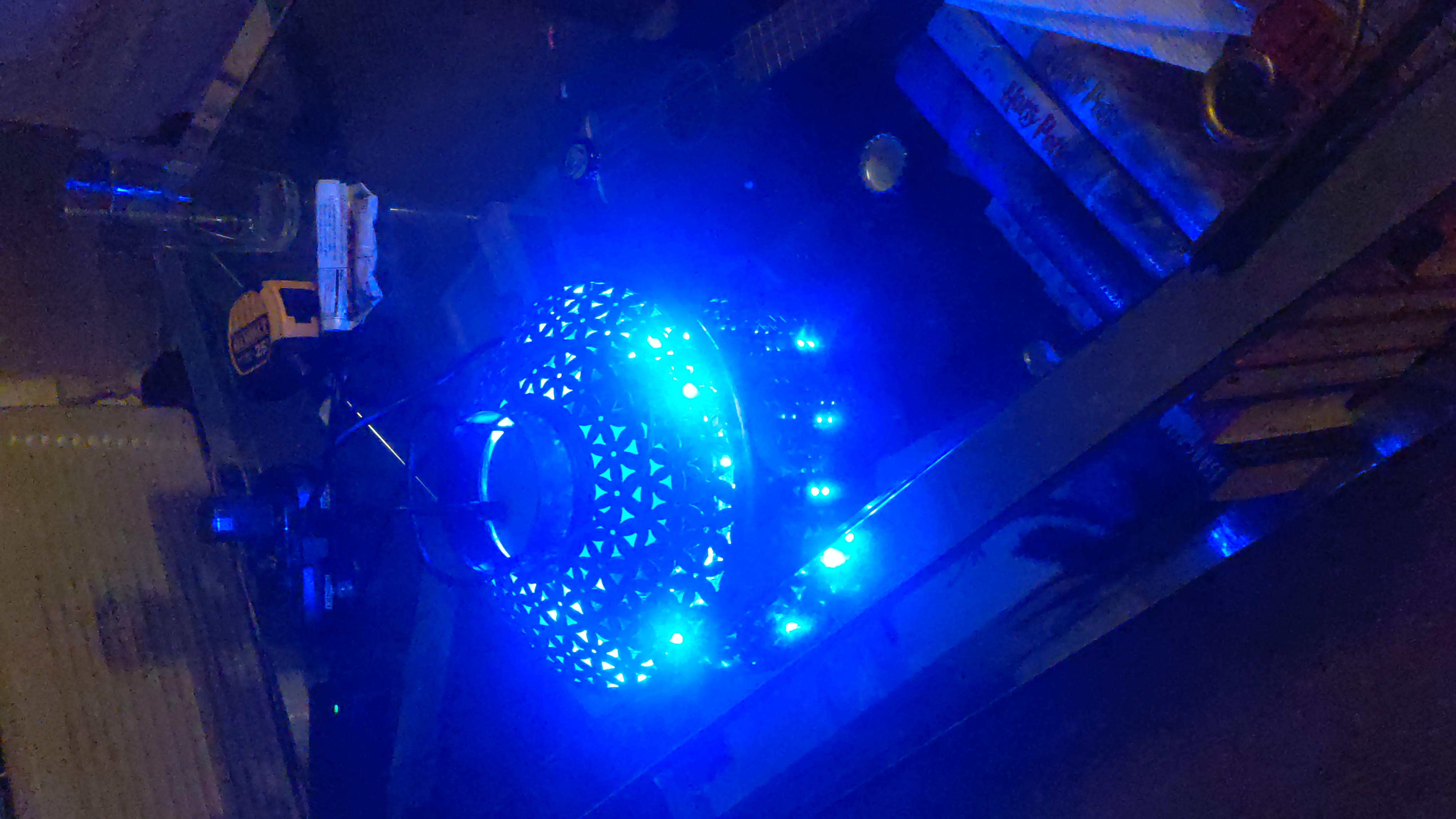
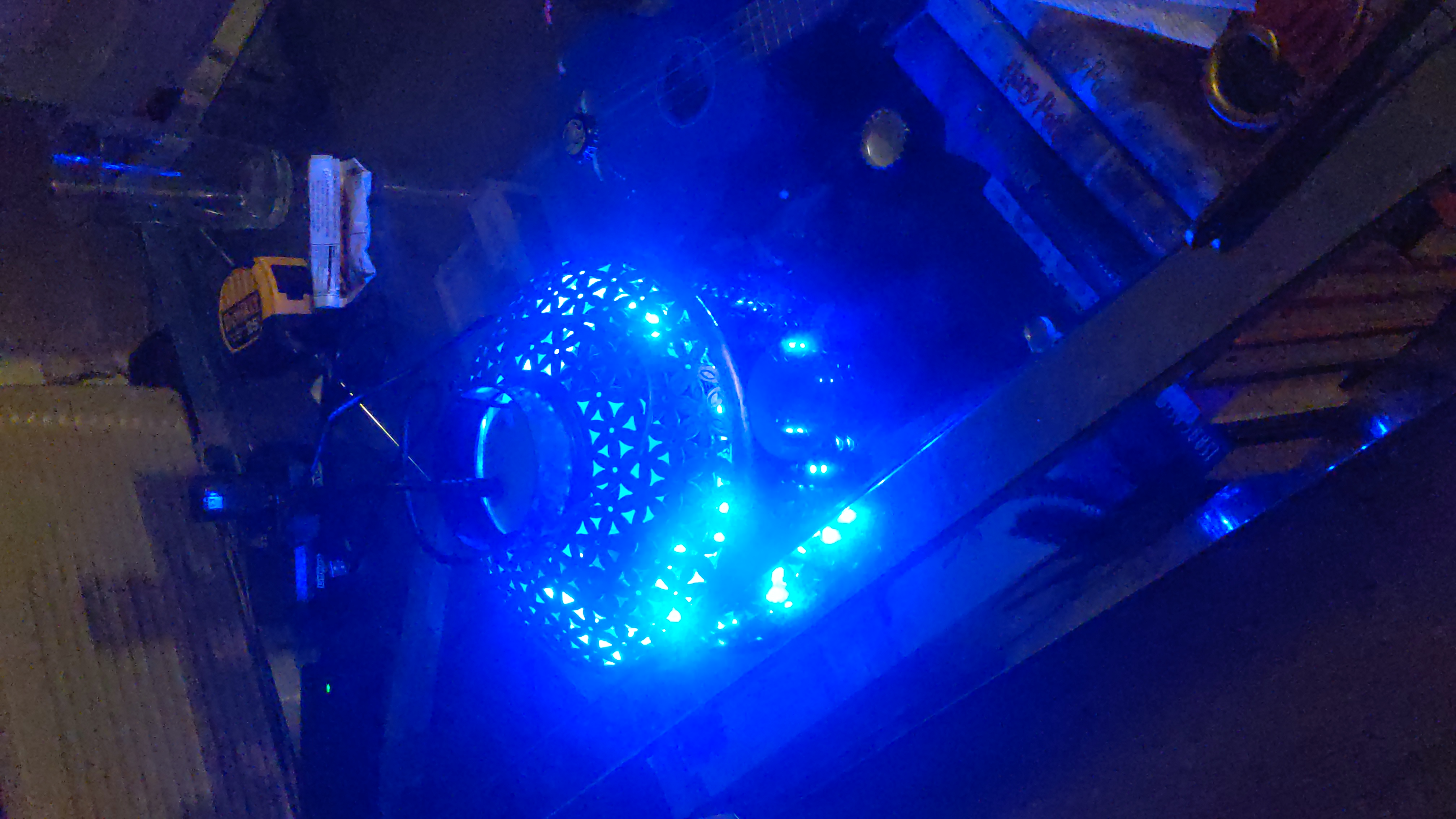
While traveling in India I came across these nice looking tin lamps.
It is sometimes called a Degchi lamp. Since I am not a fan of open flames so leds will have to fill in the role of a candle. This build will be a bit rough. I will refine the lamp in later posts.
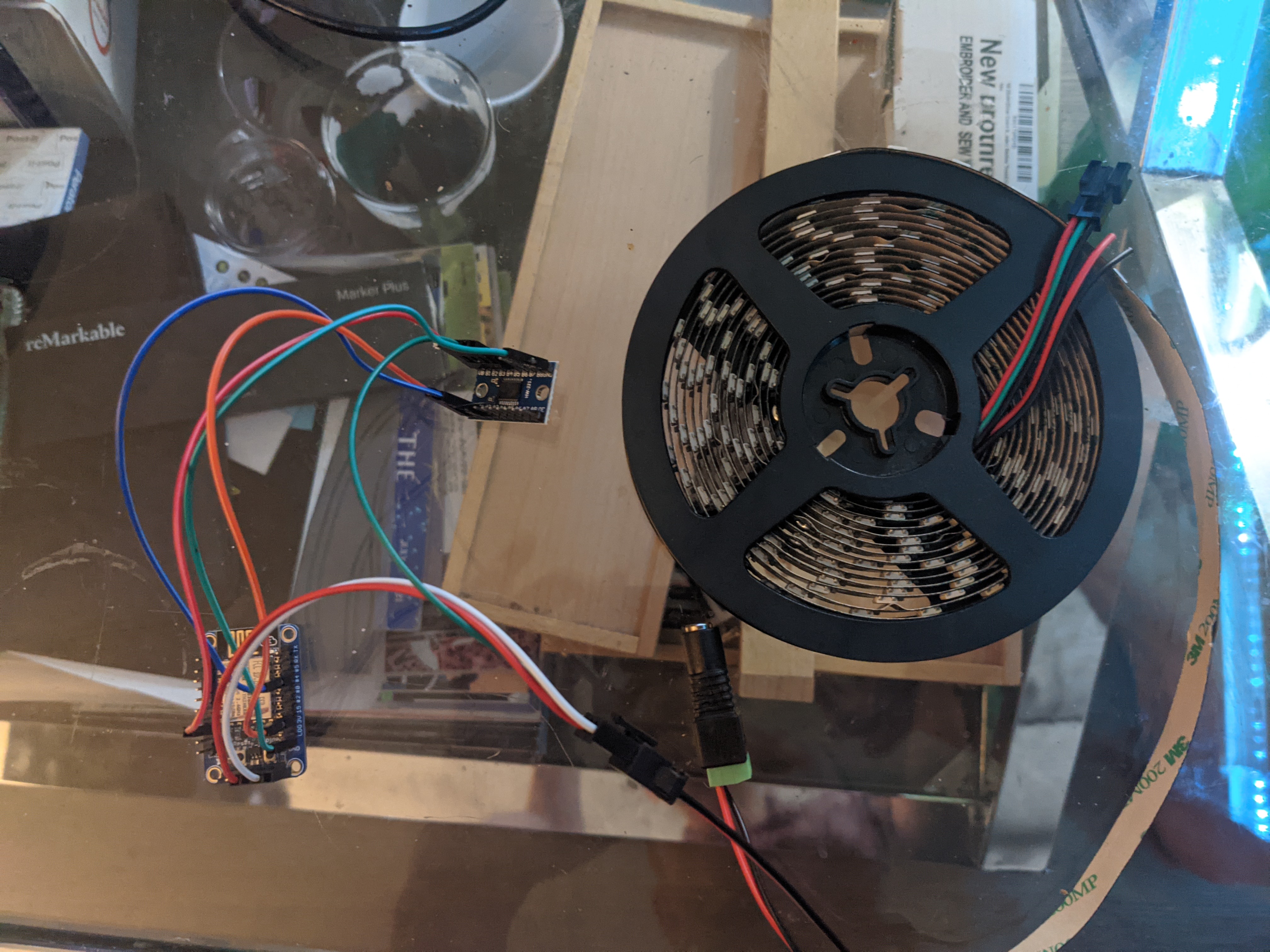
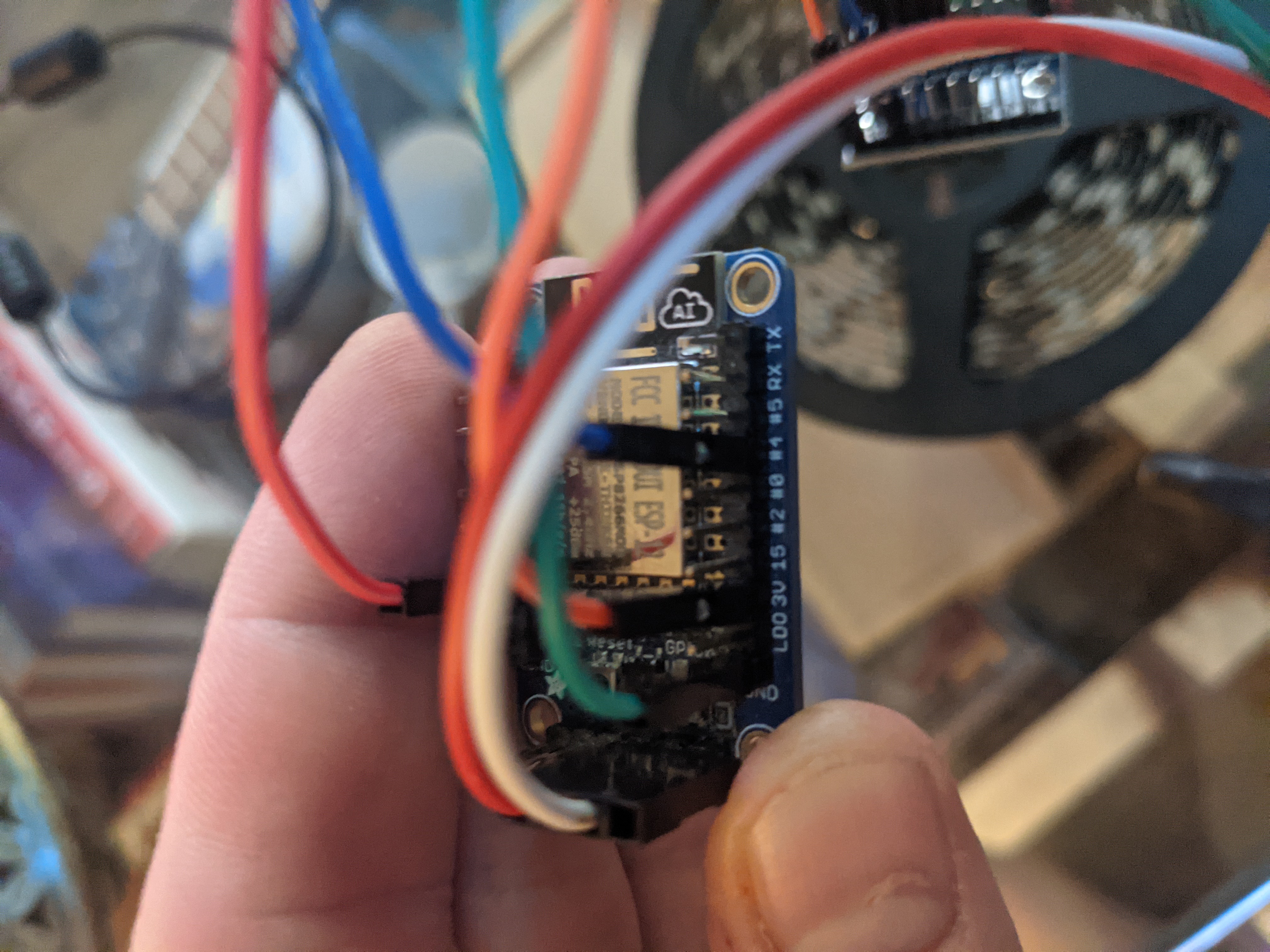
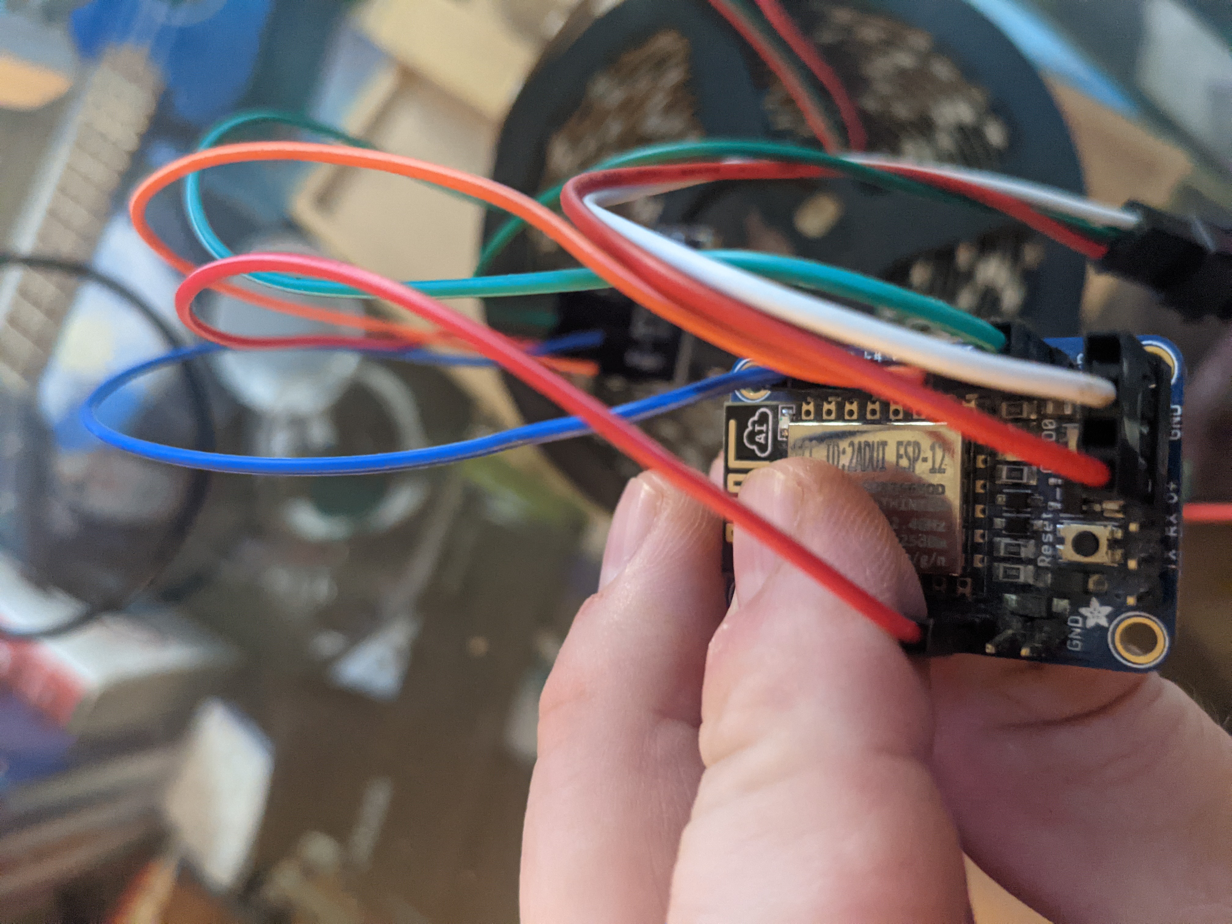
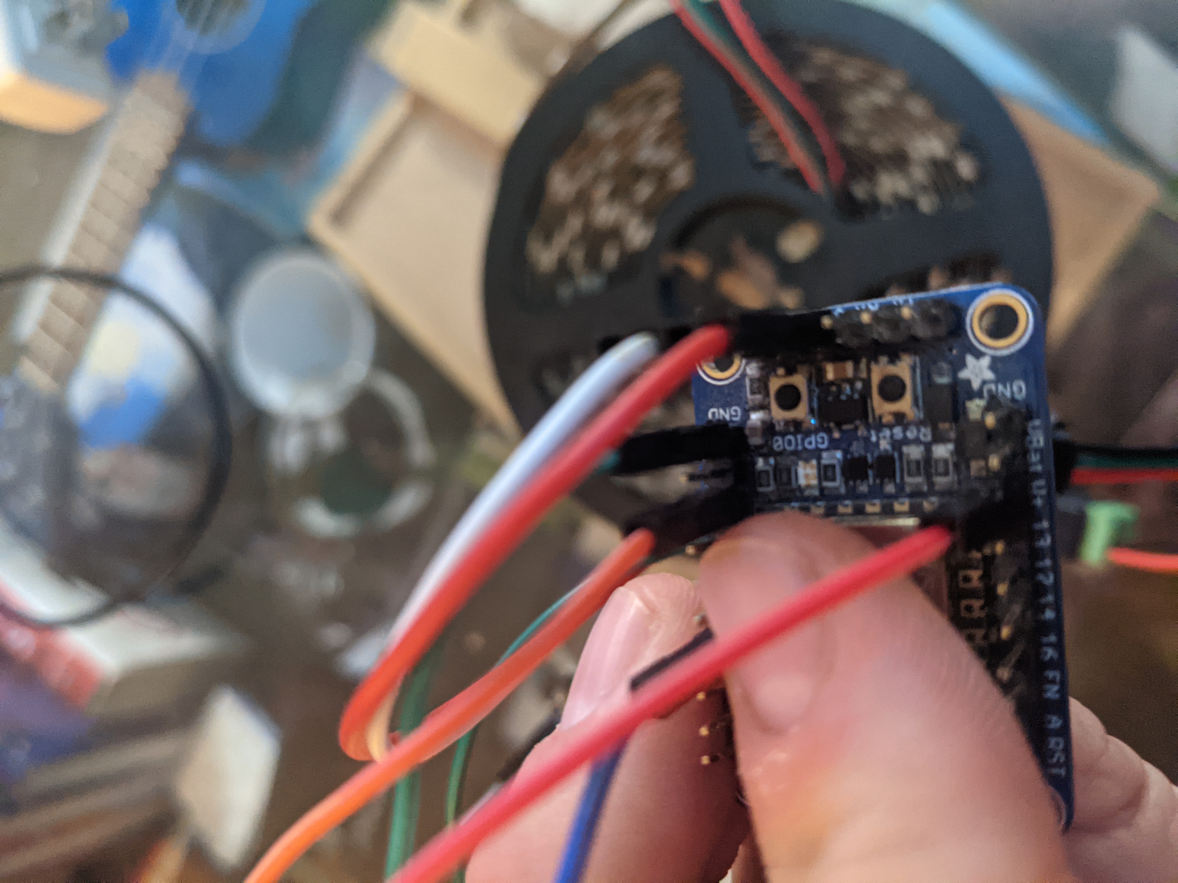
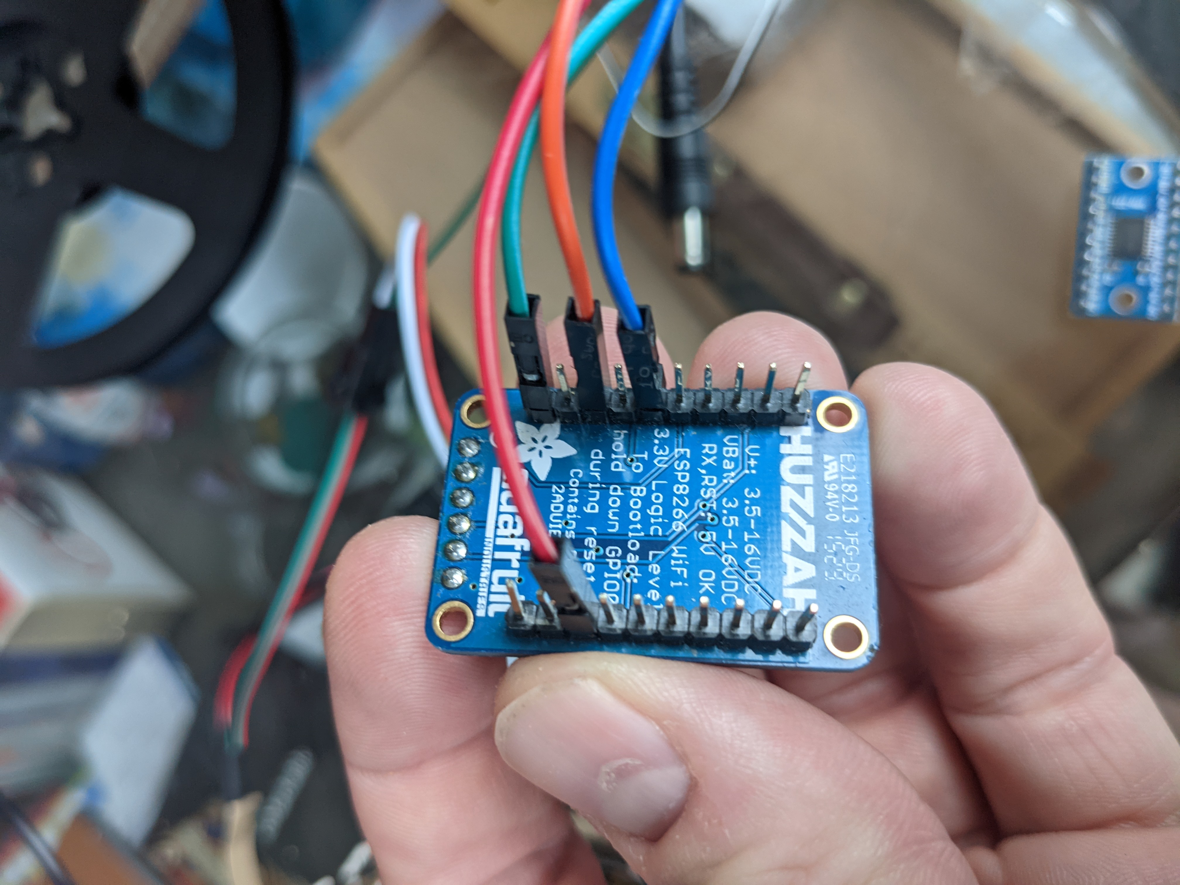
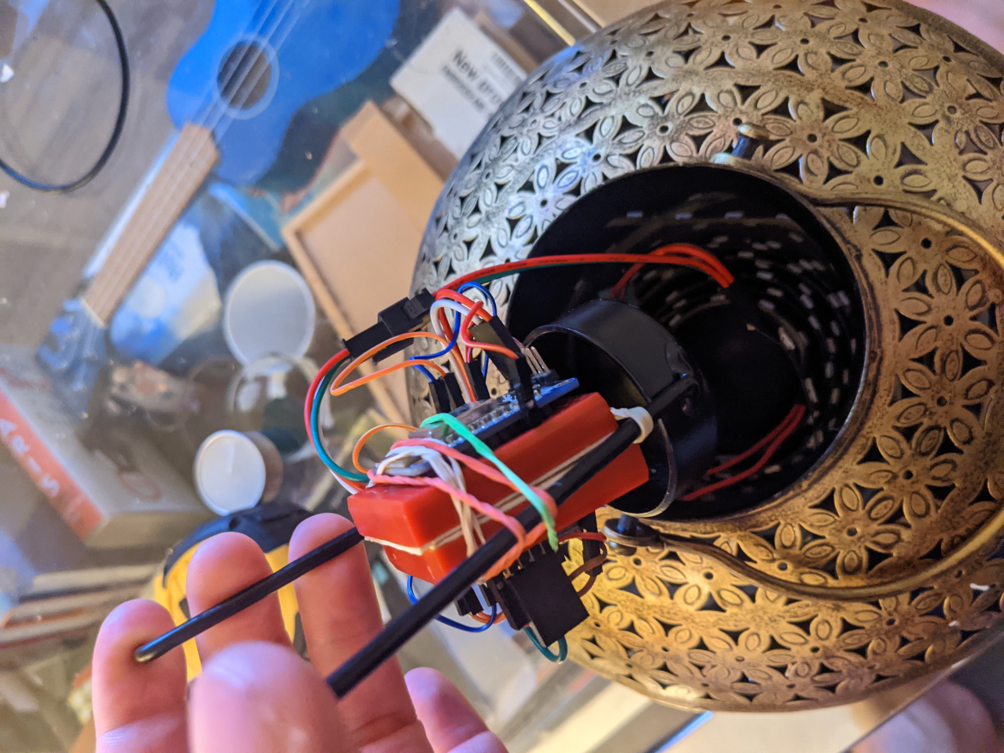
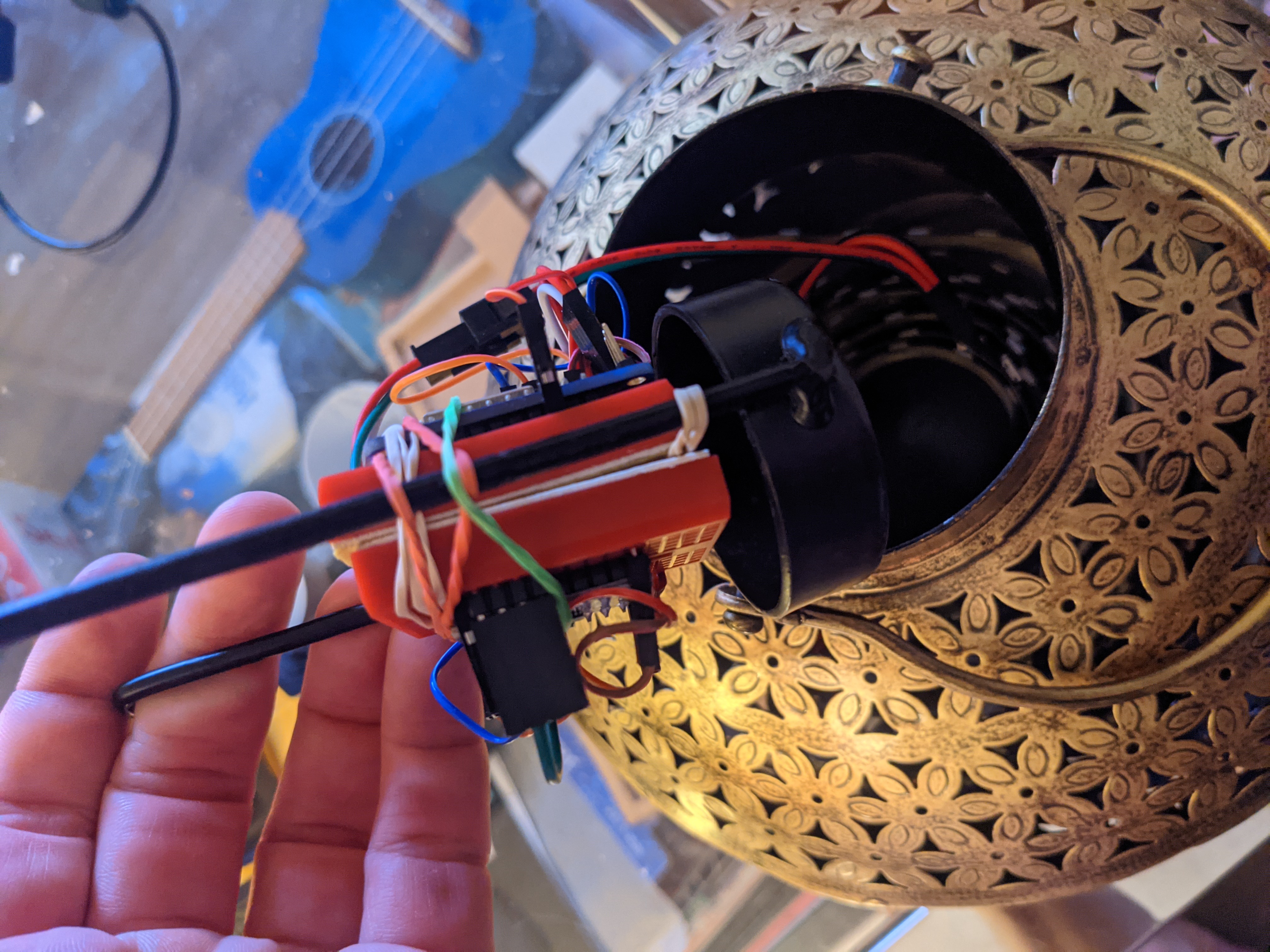
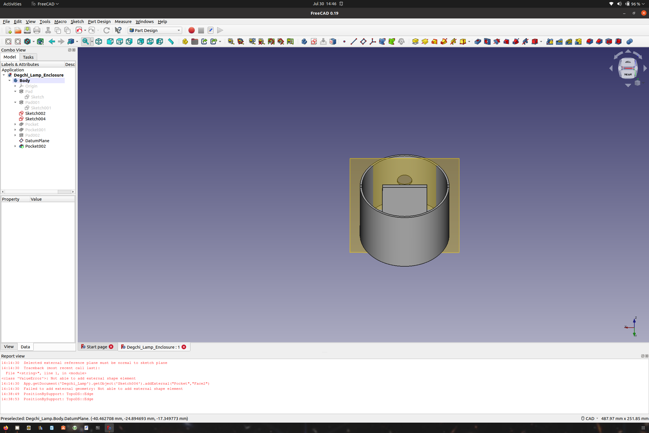
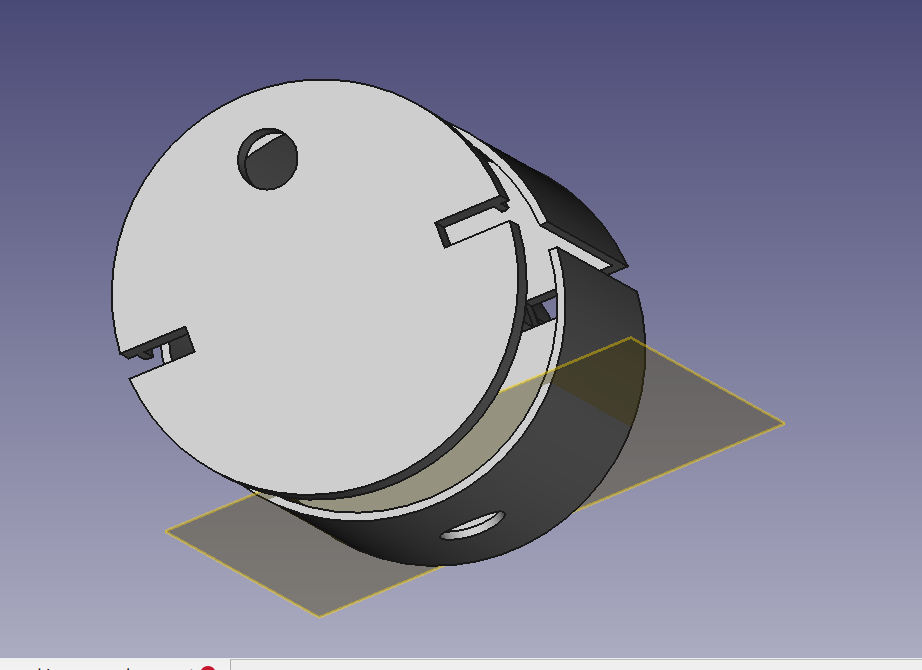
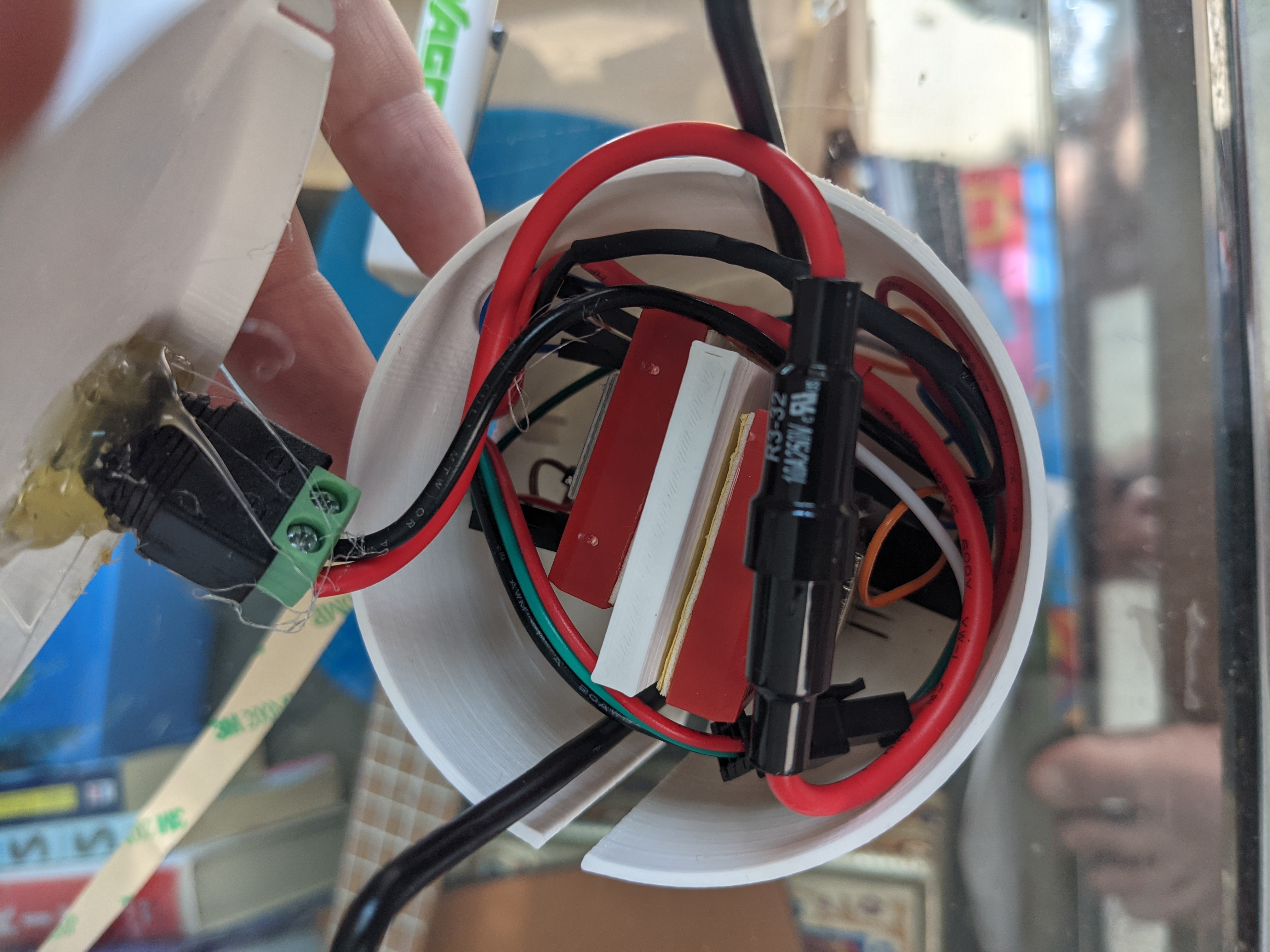
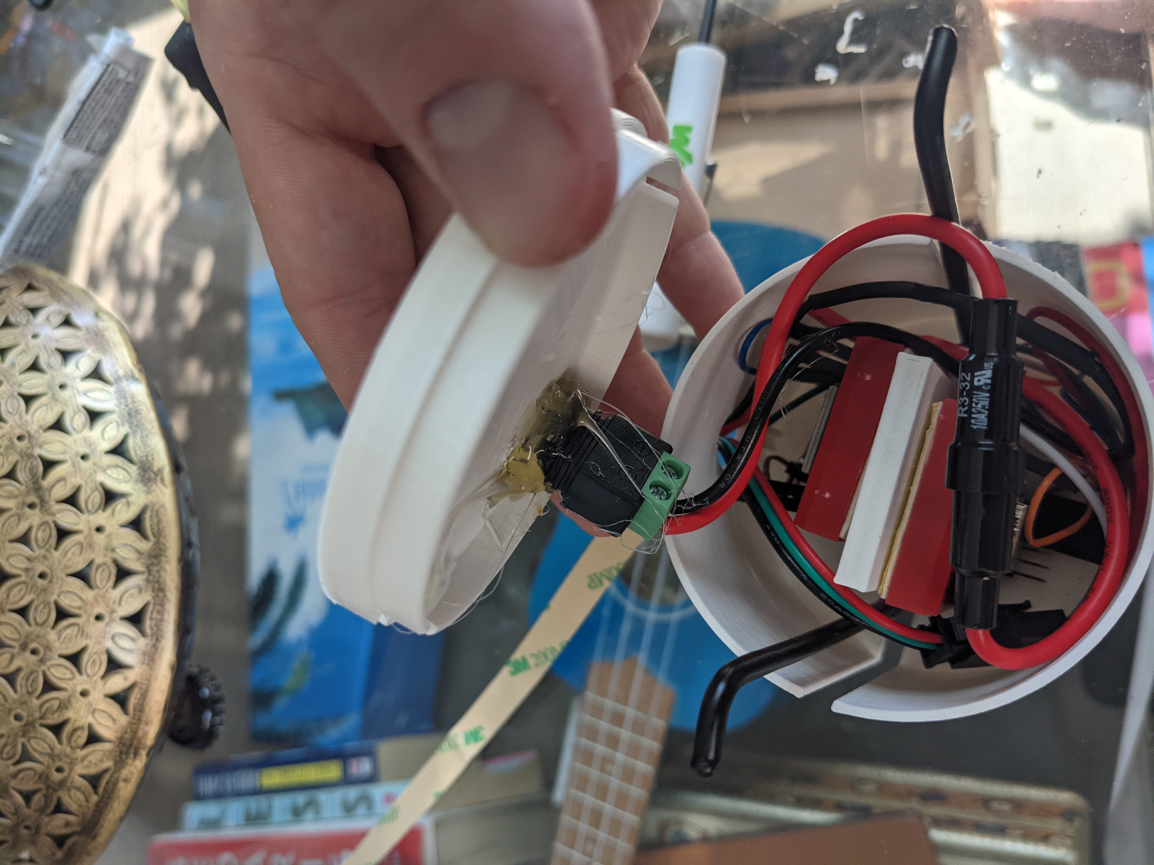
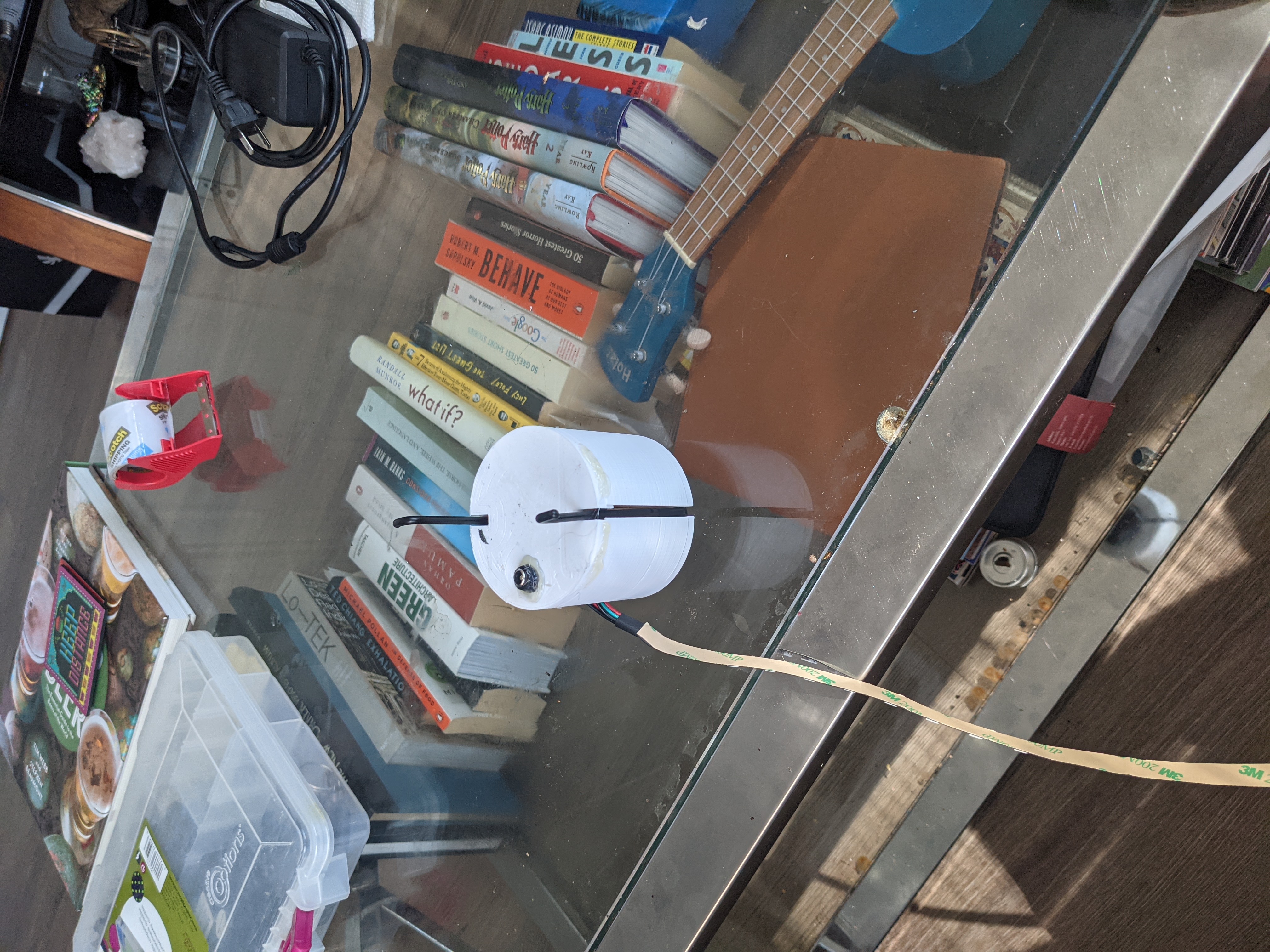
All the electronics seem to fit. A more professional version will be created when I get the parts.
Forcing all the electronics into the enclosure.
Everything is coming together.
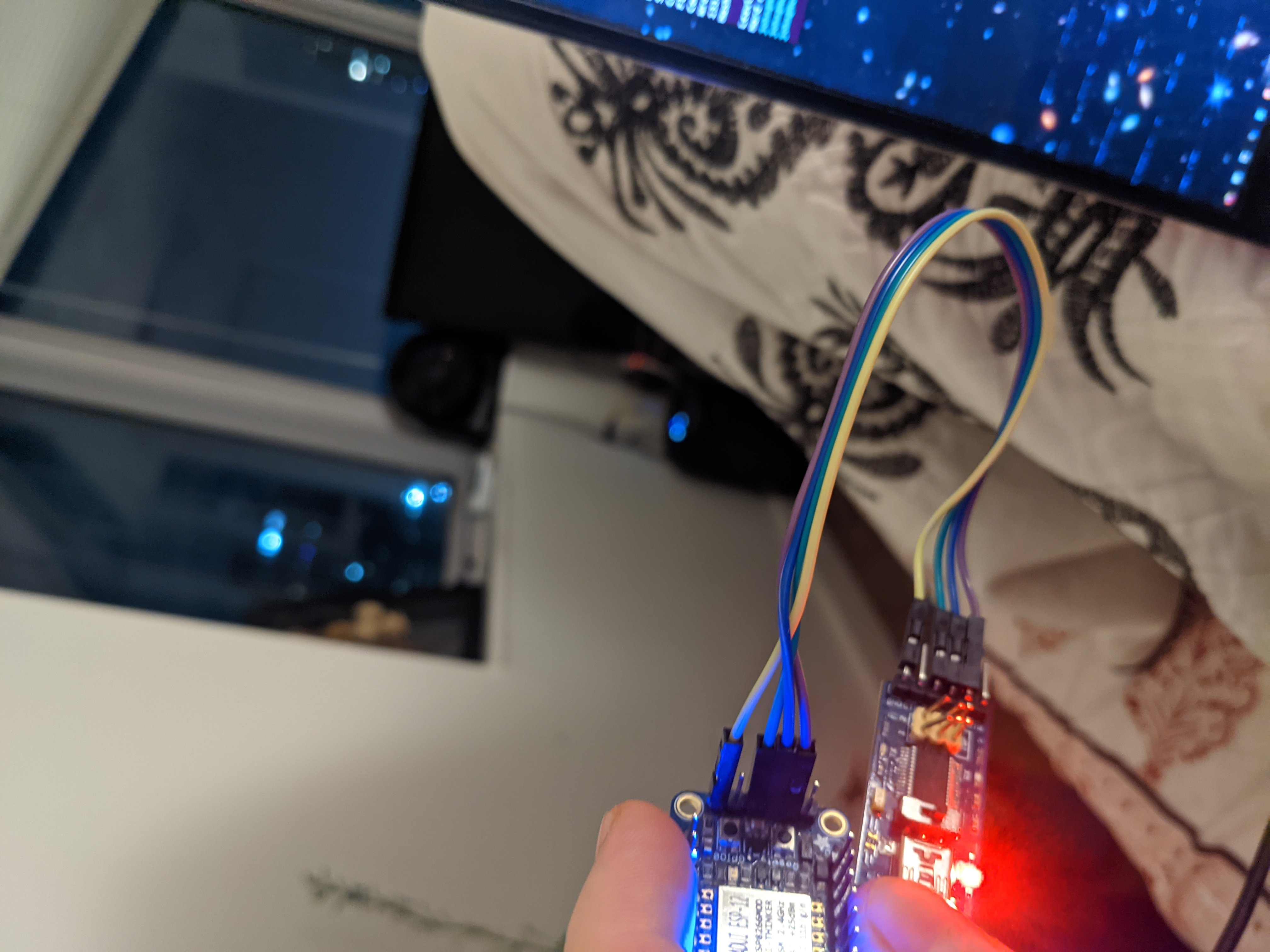
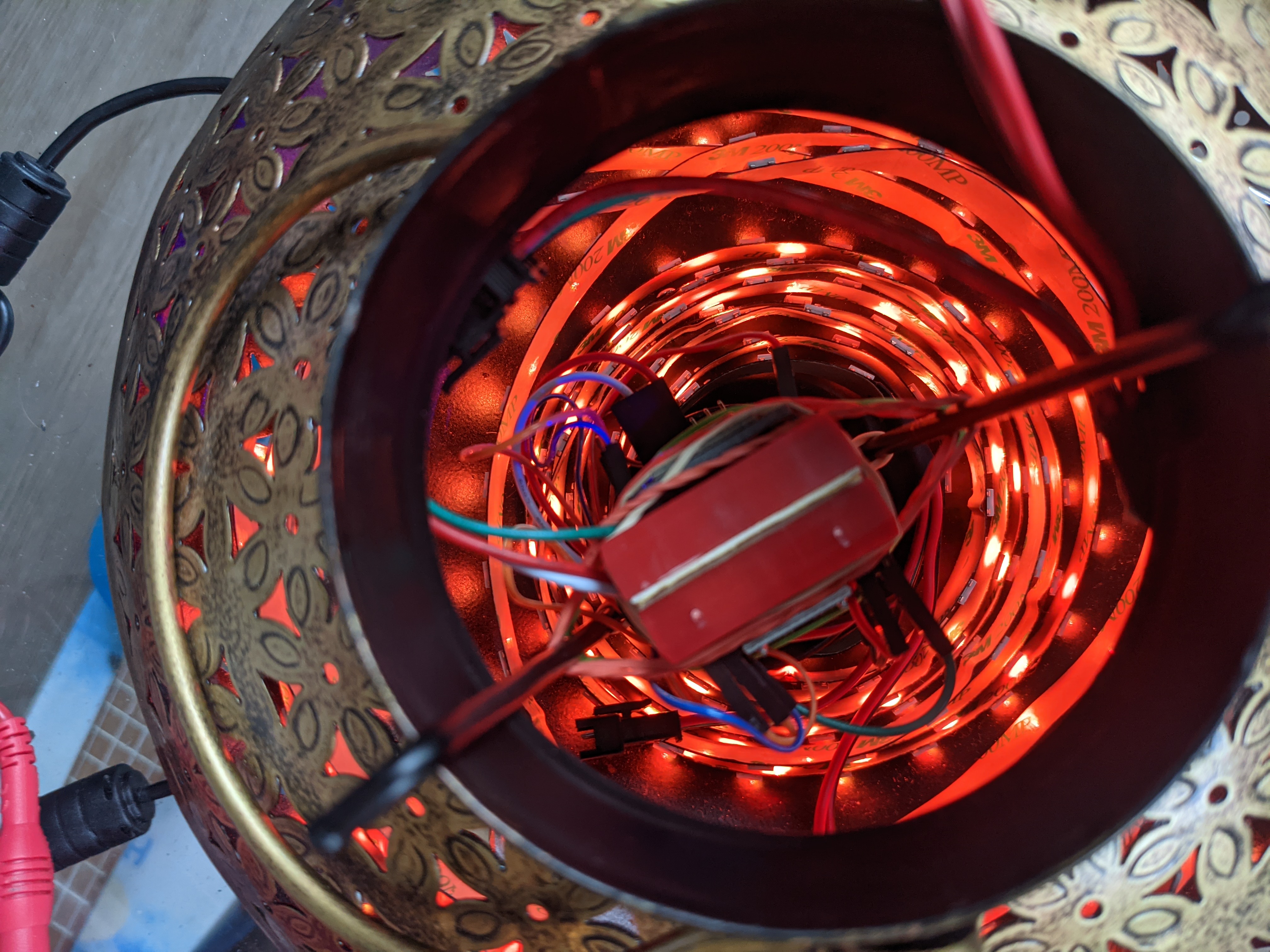
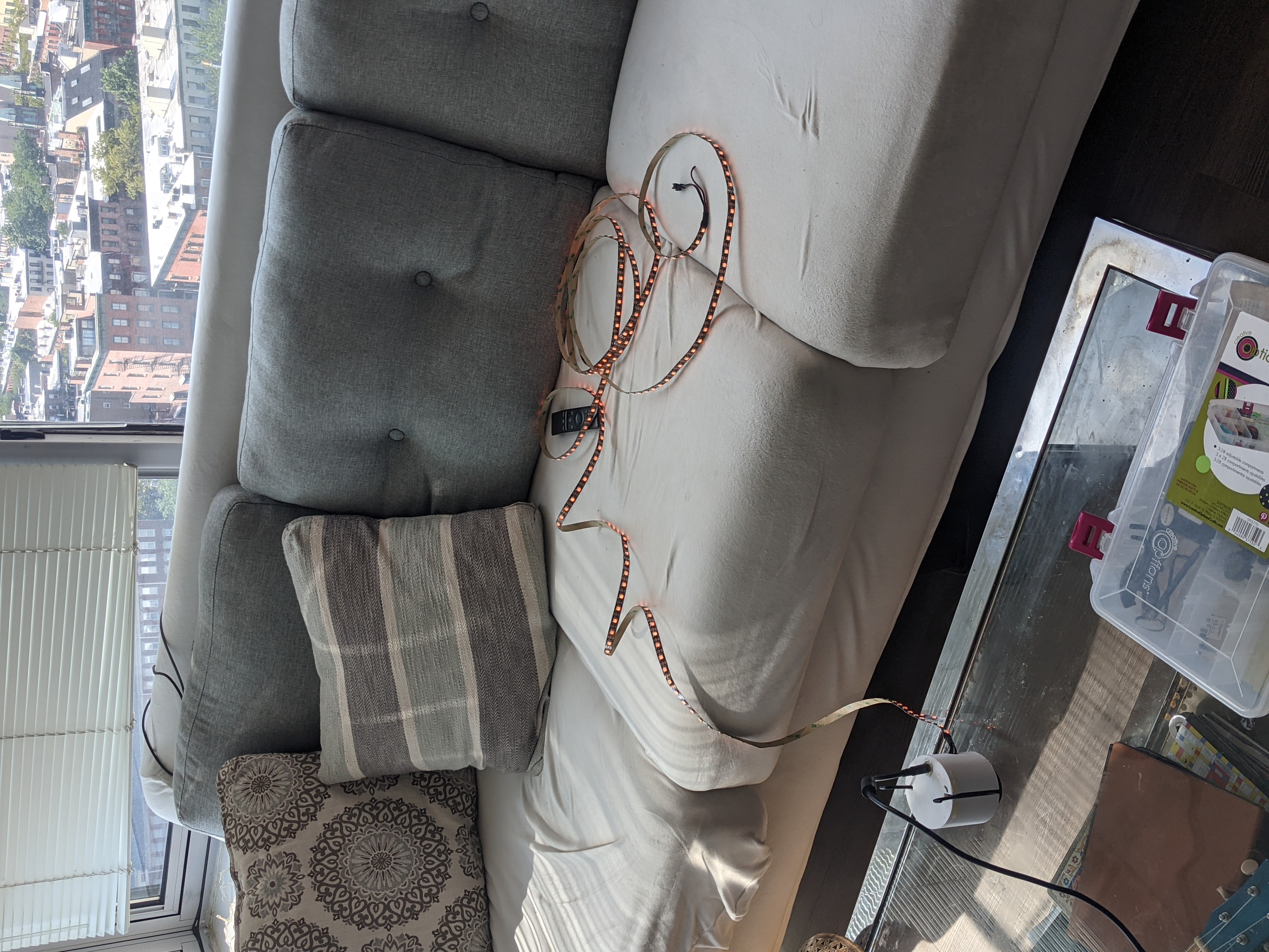
Power on testing
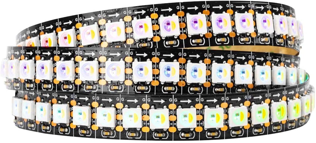
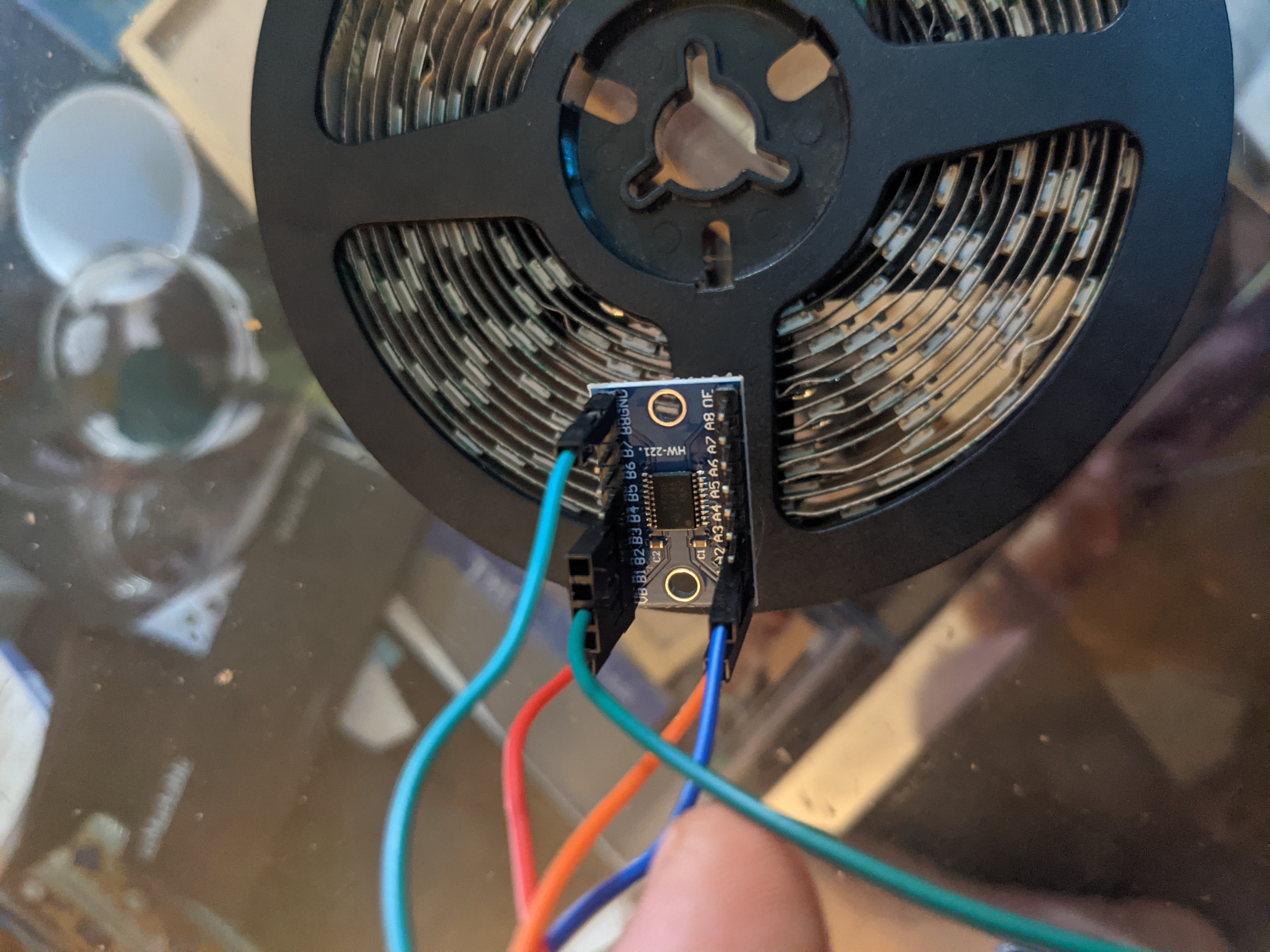
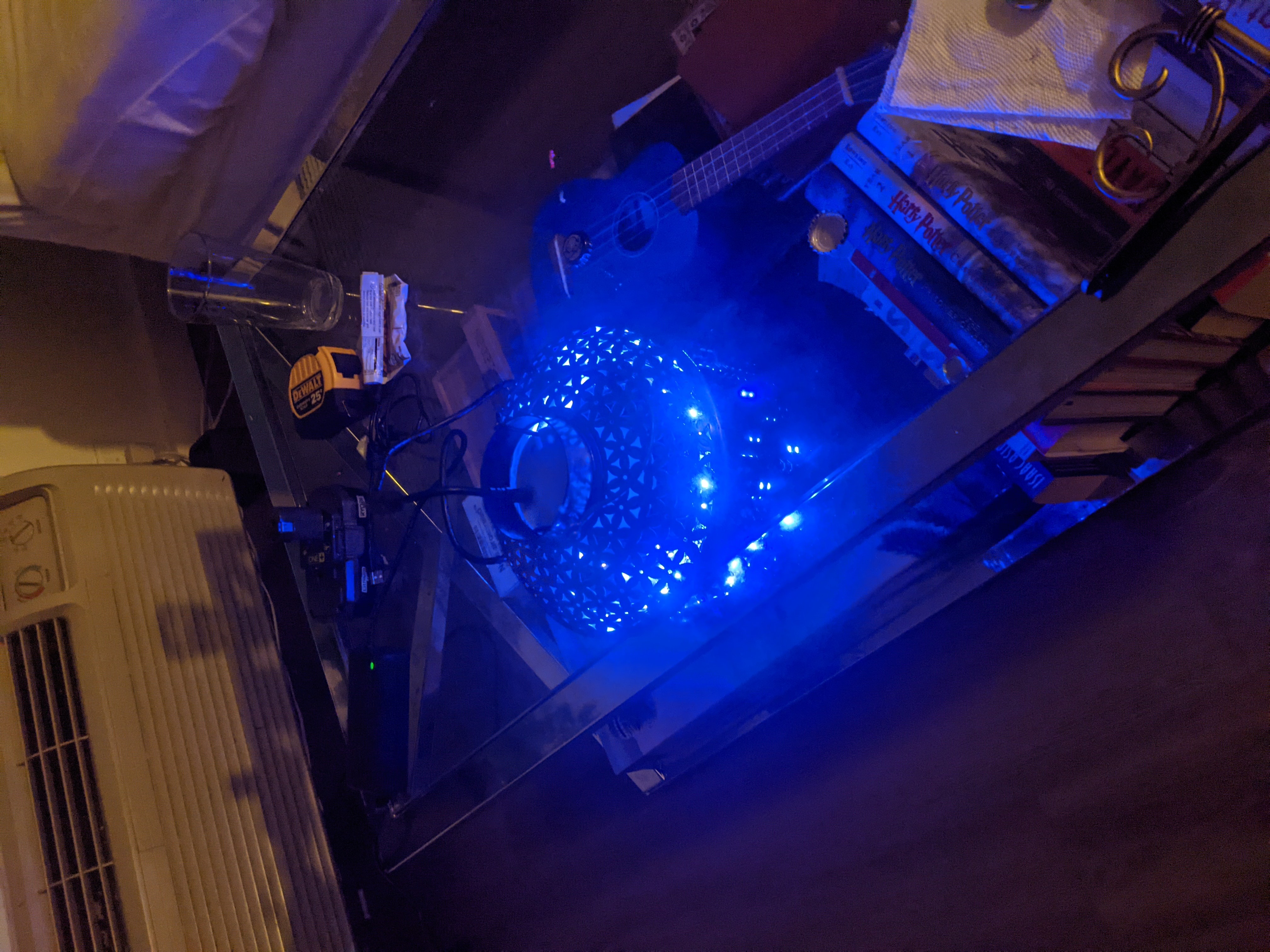
Led Mounts
The inside of the lamp is coated in a thick non conductive coating. For the time being the led strip is just placed inside the lamp body.
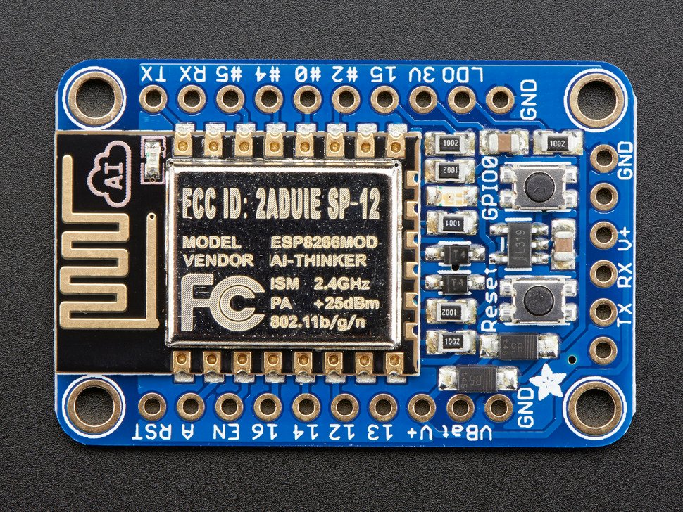
Connecting to WIFI
WLED 13.1 has some trouble connecting to wifi networks.
Set wifi control channel to a fixed channel. e.g 1
Change channel width to 20 Mhz
Bind to static ip in router
Add the same static ip in wled wifi settings
Results
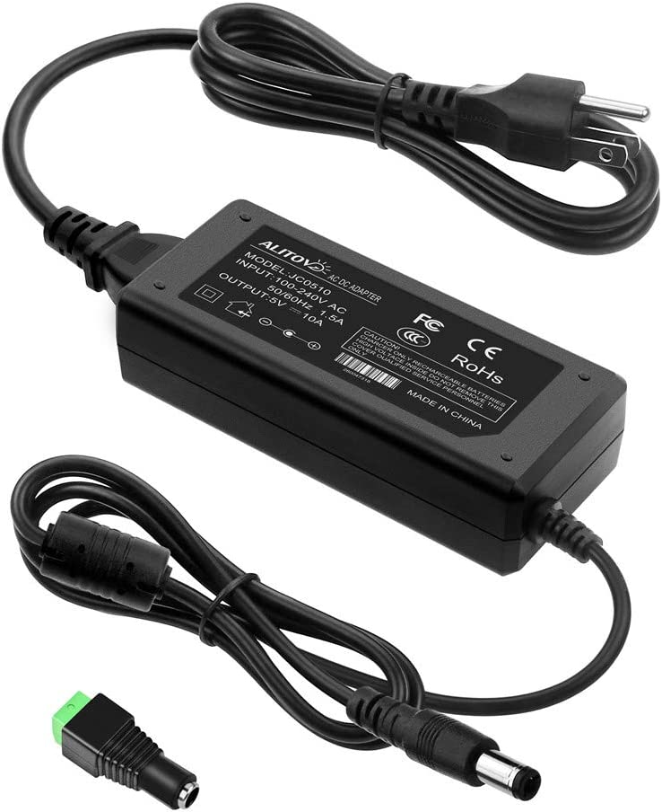
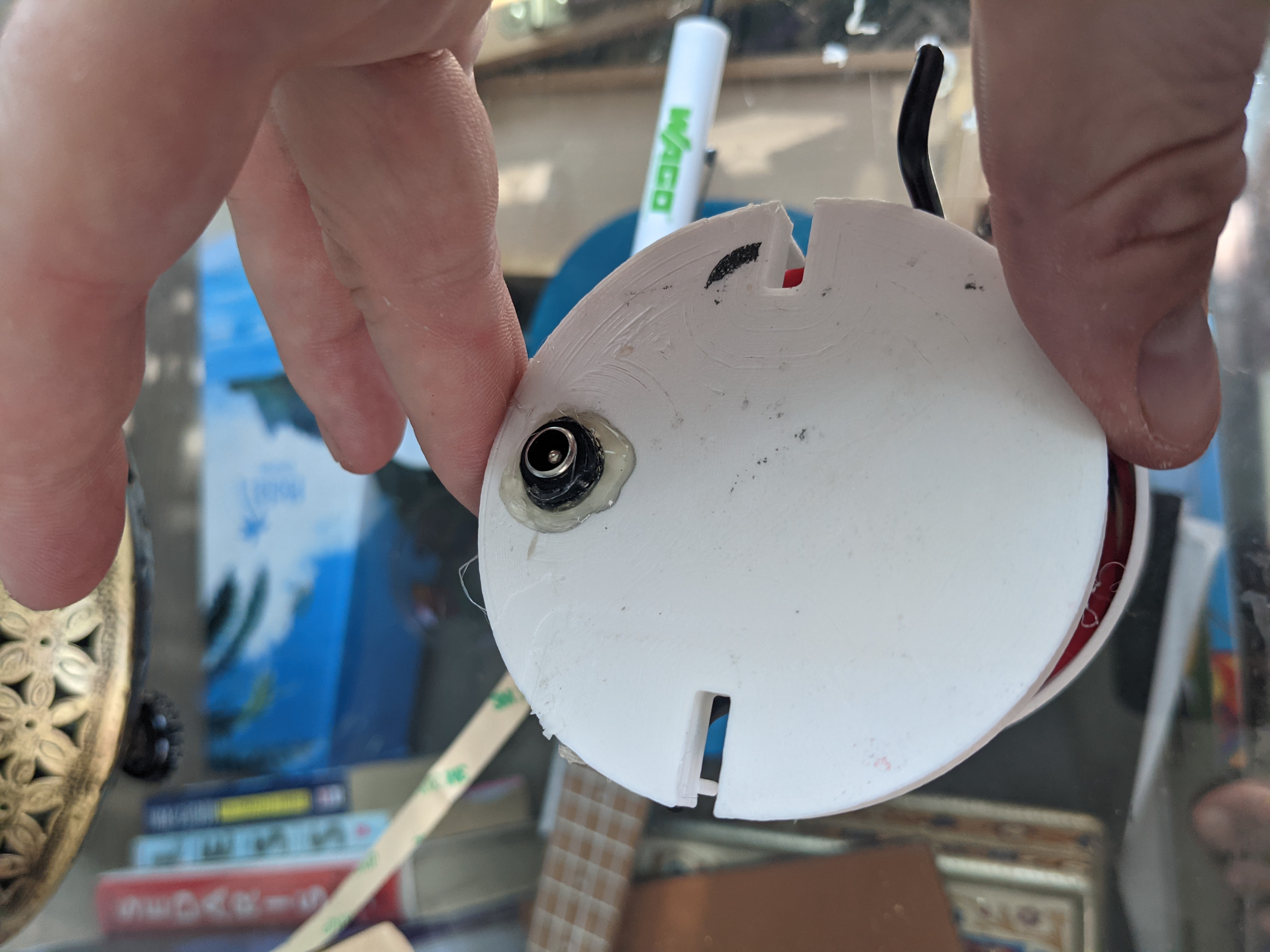
I am not a fan of this very large black power cable. I will replace the power cord with USB-C. After measuring the power usage of the lamp at peak load it looks like USB-C is a good option. Peak load 0.6 Amps This will be covered in a follow up article.
This device has the rtl8812bu chipset and you will need to do a little more work to get it working. Thankfully there is a working driver available for it here: https://github.com/cilynx/rtl88x2bu
To get it working, you will need to first install some packages and check out the Git repo: