Materials
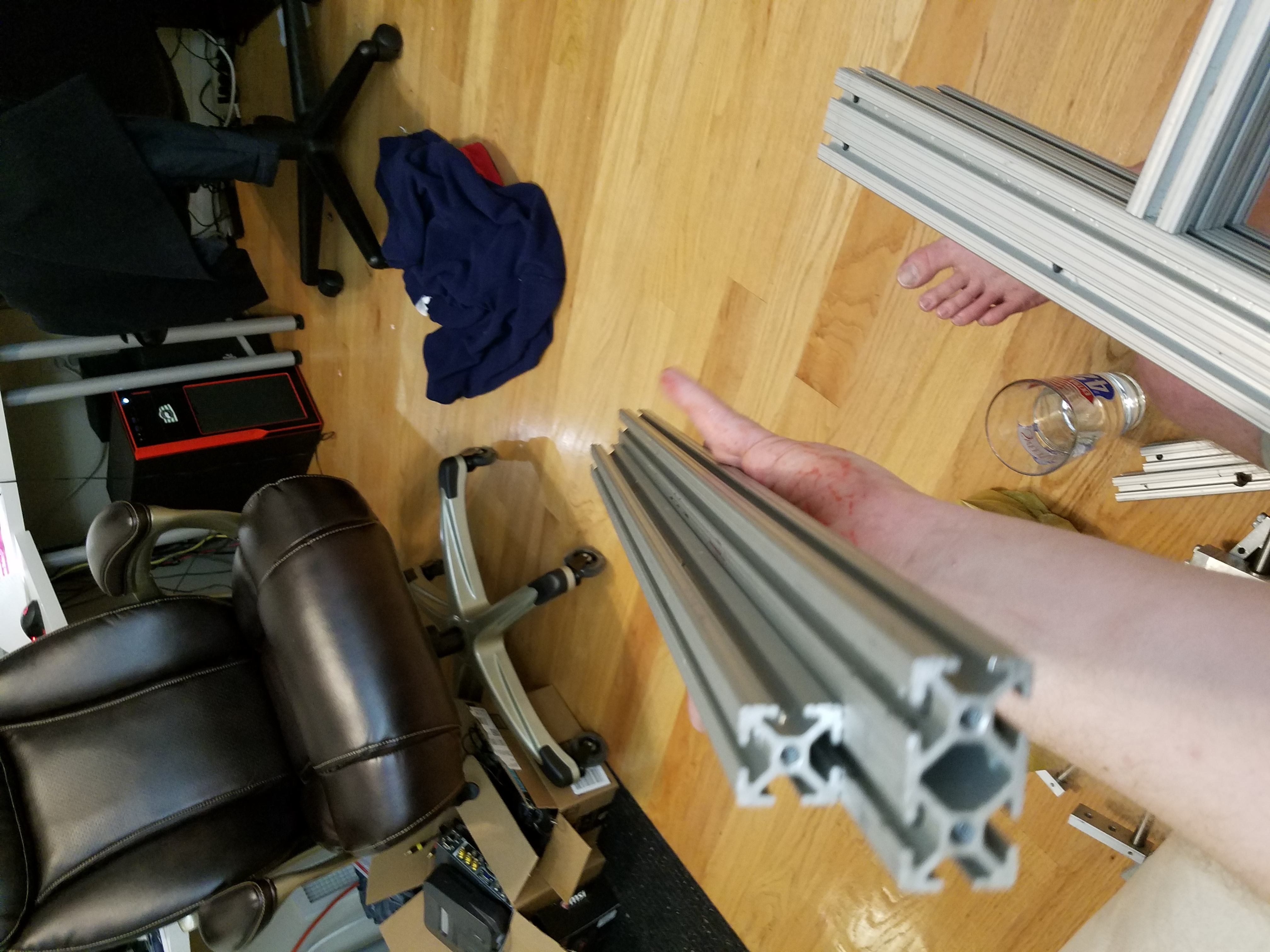
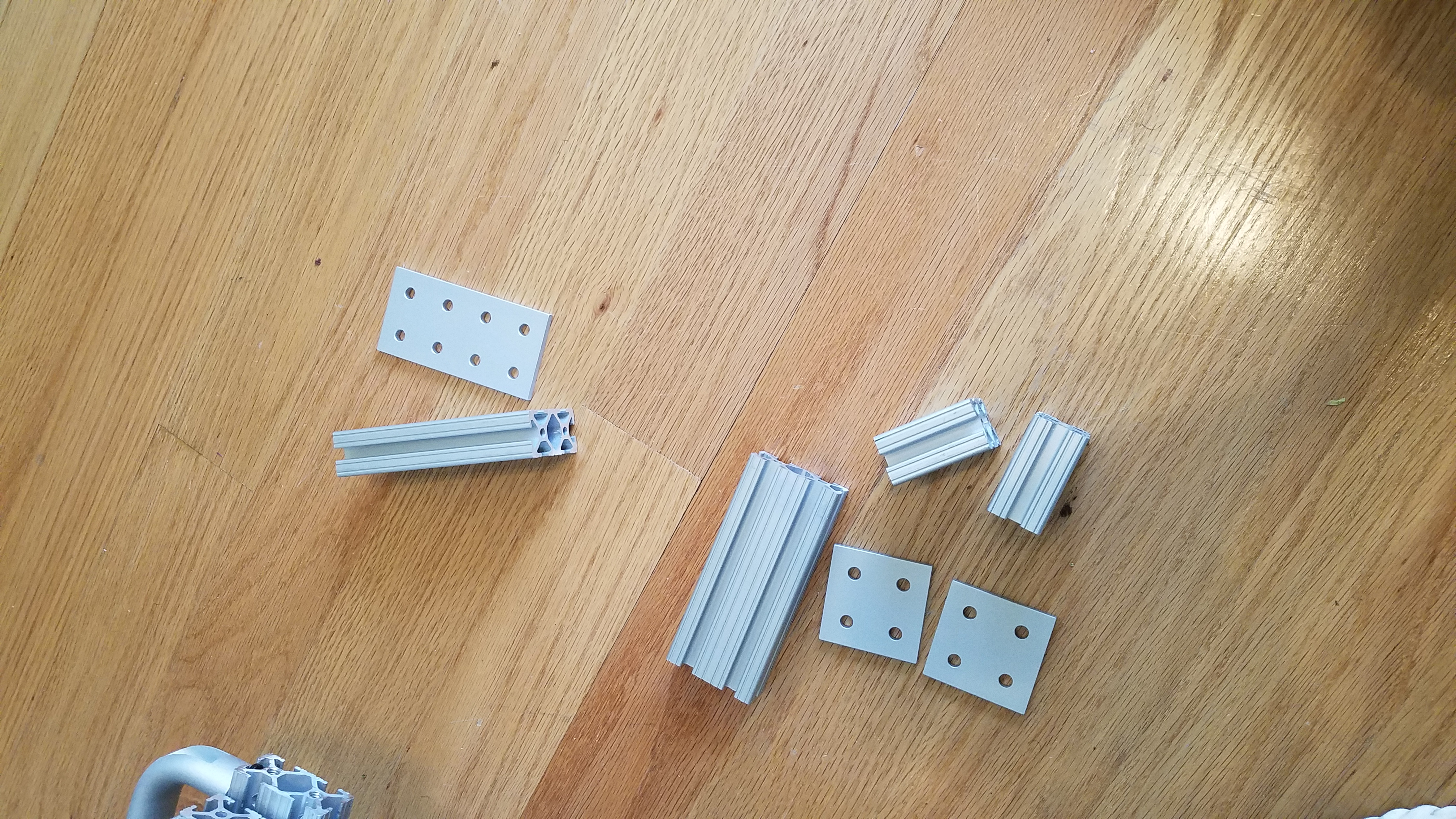
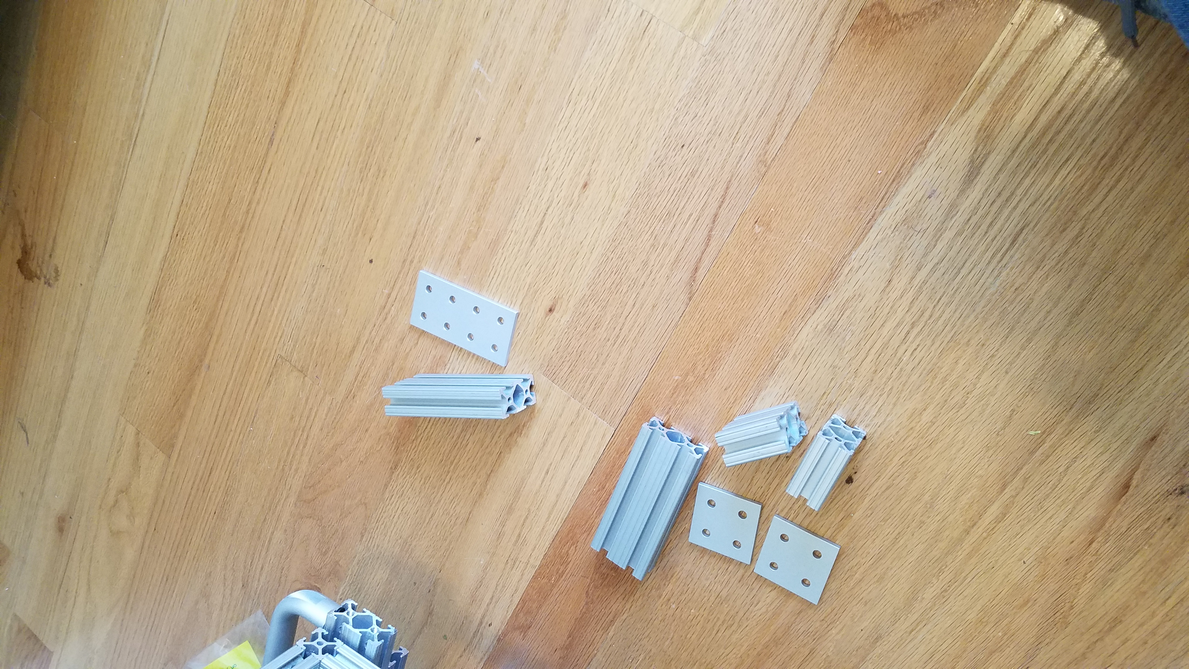
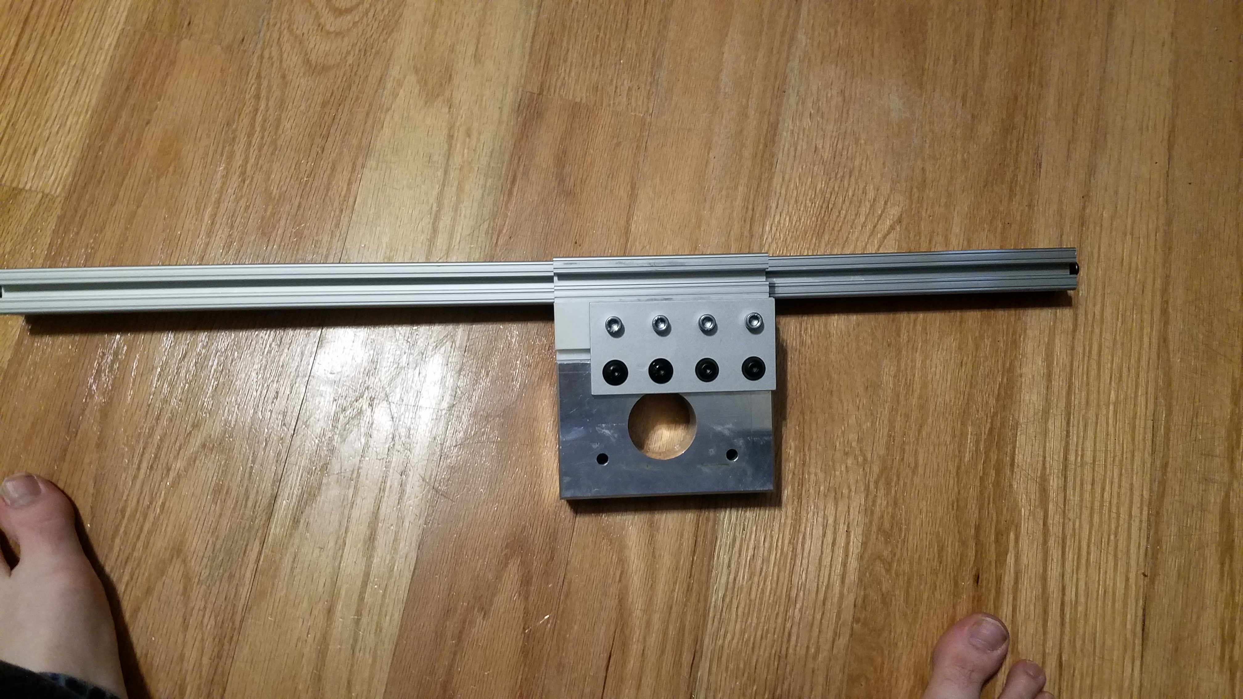
The entire frame is build from 1in x 1in x 24in 80/20 T slot. These can be obtained from https://www.mcmaster.com/
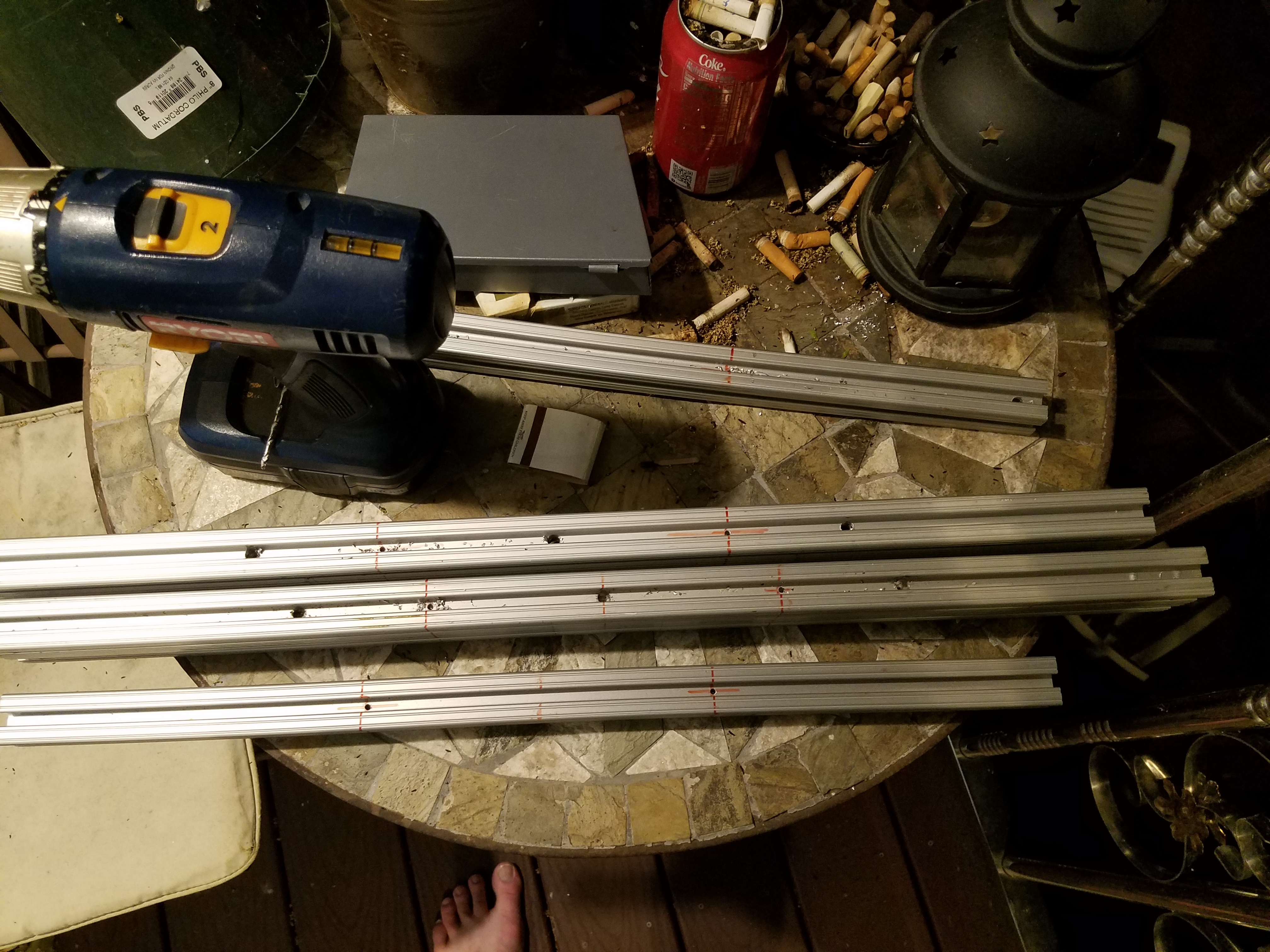
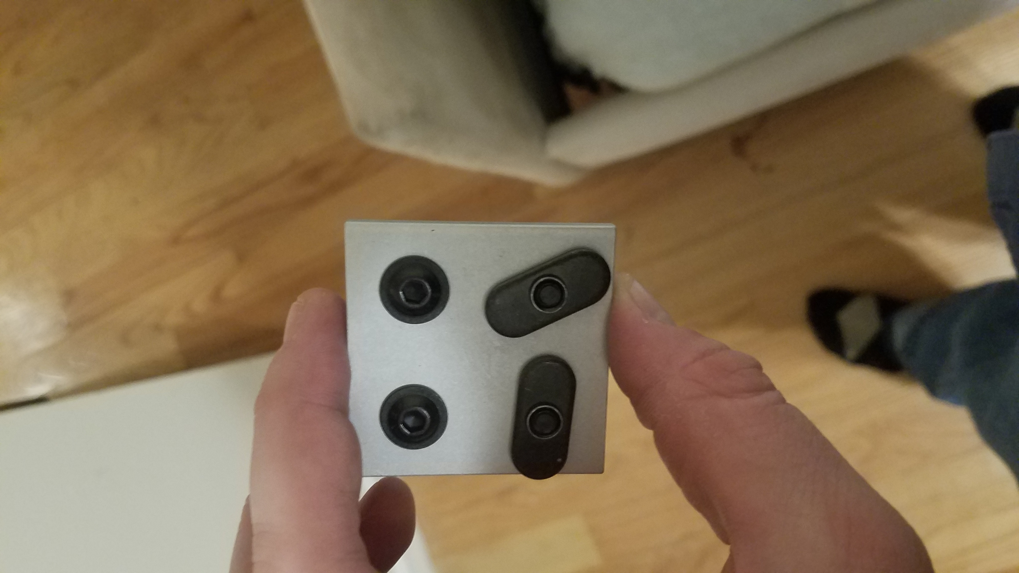
The rails are joined with a combination of “Flanged Button Head Screws”, T slot nuts, and tapped ends. Any Tslot end that had to connect to another Tslot at a 90 degree angle had it’s end tapped with a 1/4-20 tap. The cooresponding Tslot to be joined had an access hole drilled 1/2 in from the end. This access hole allows me to tighten “Flanged Button Head Screws” with a hex wrench.
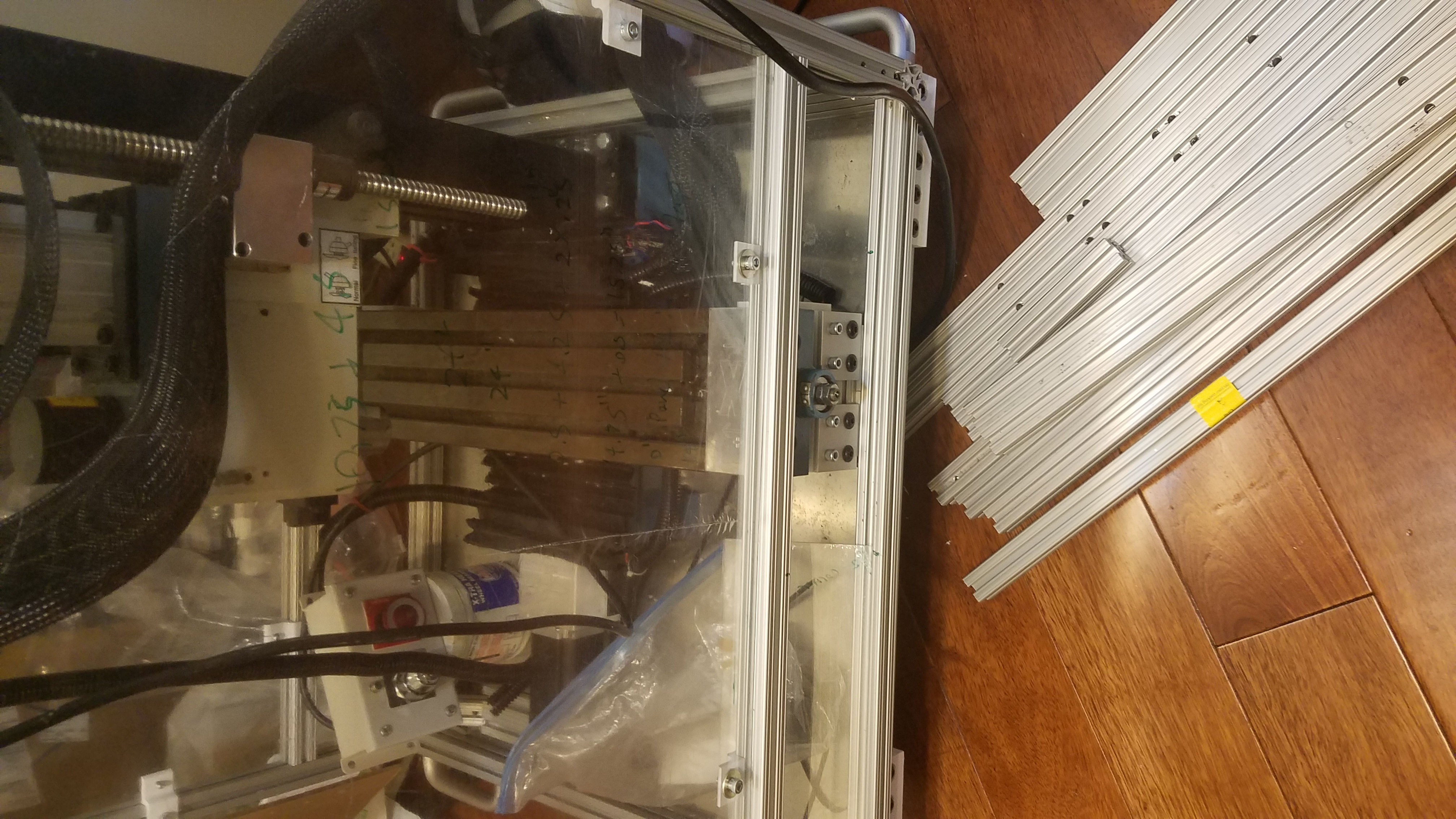
Filename: 20180621_192035.png
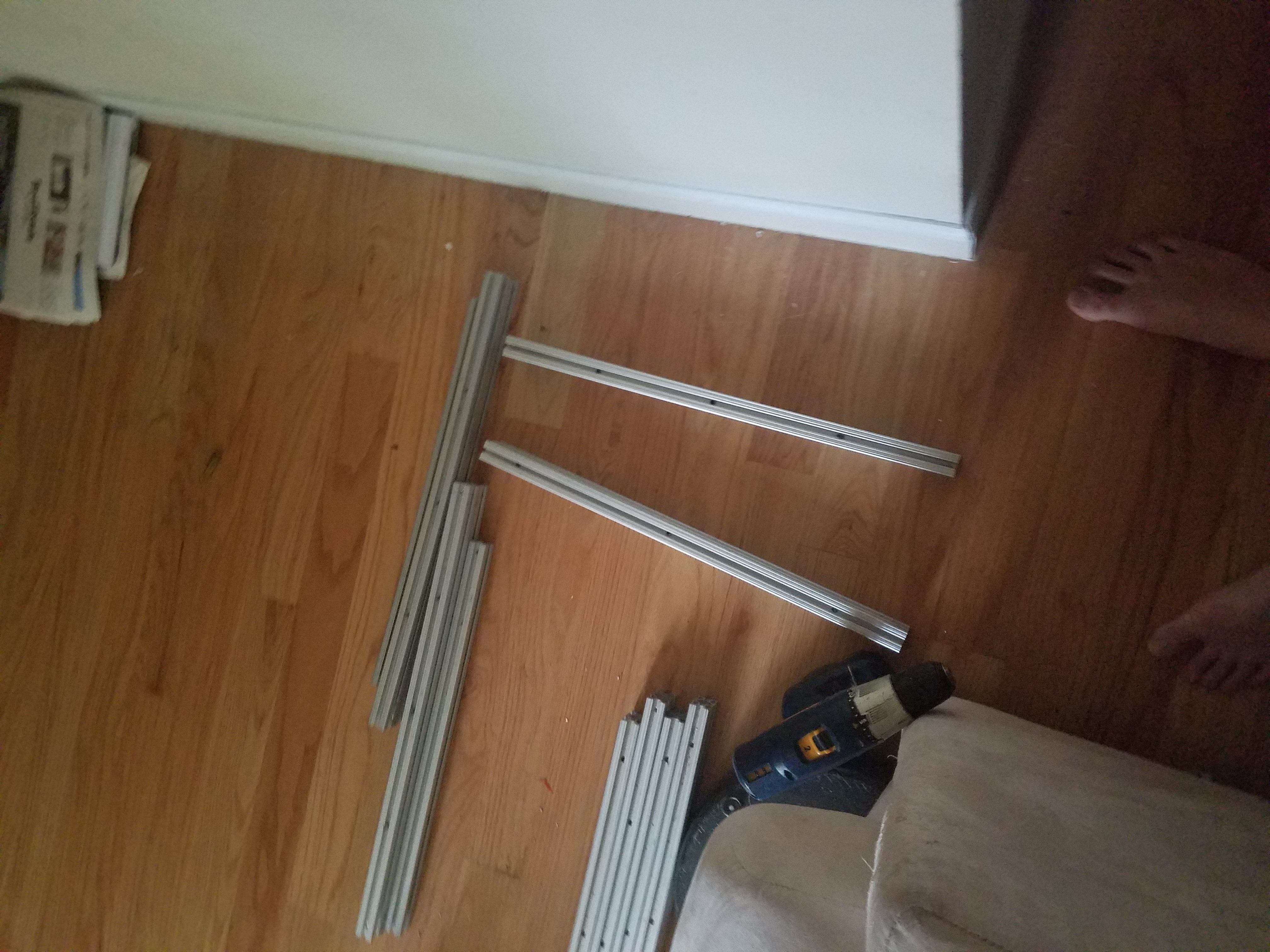
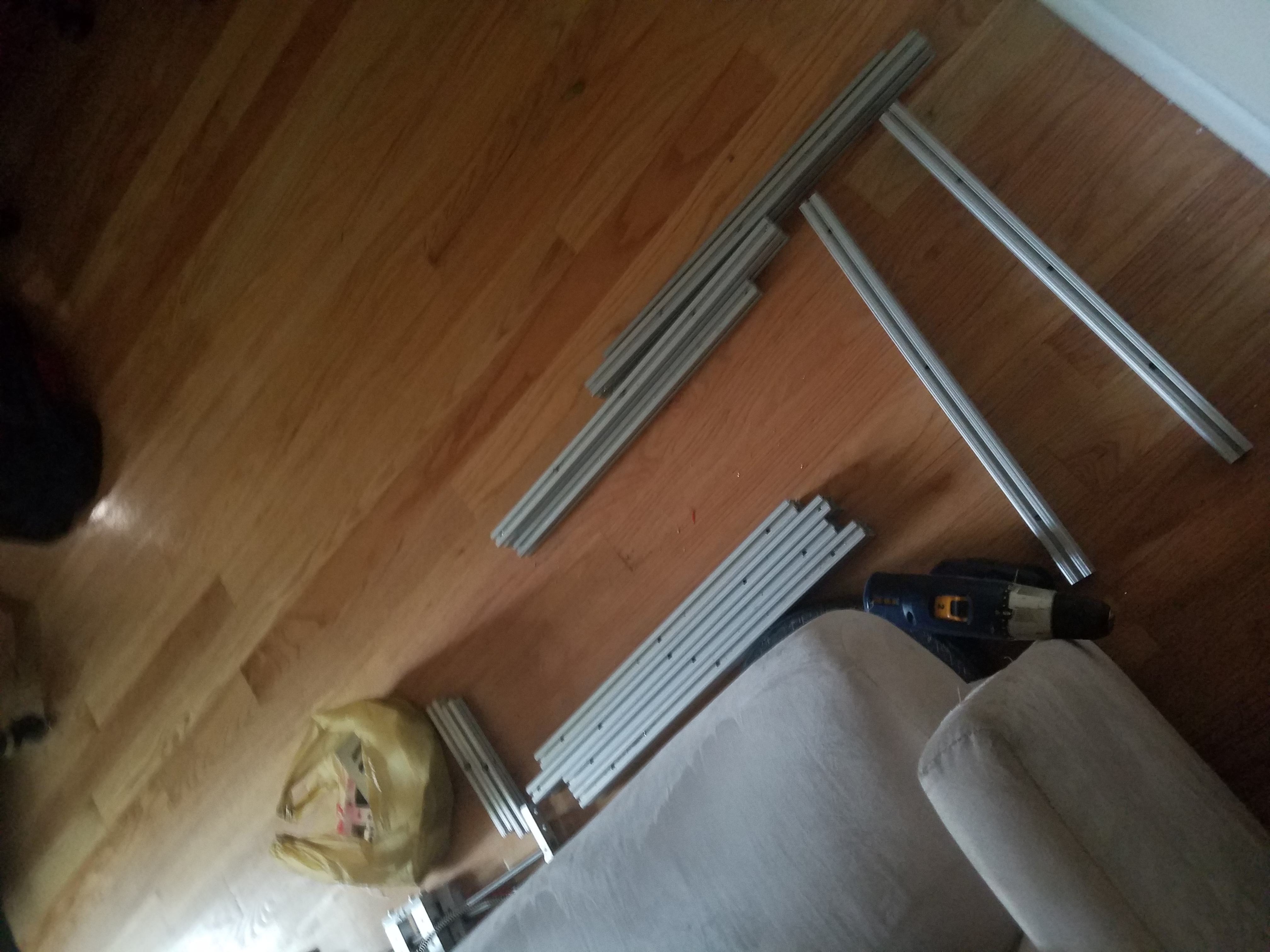
Description: A collection of cut aluminum extrusions laid out on the floor, the materials being prepared for the frame of the CNC machine.
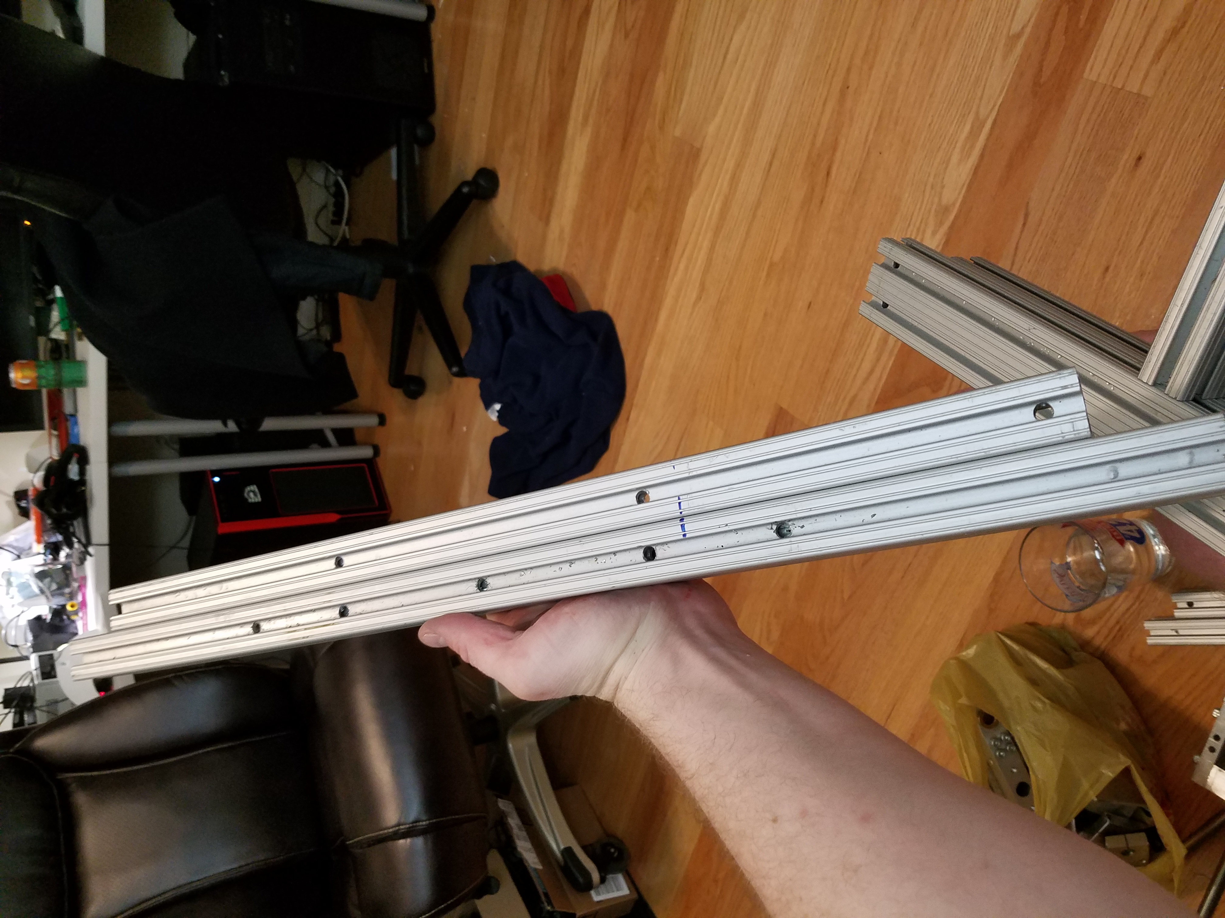
Picture of the drill holes on the bottom front of the frame.
Base
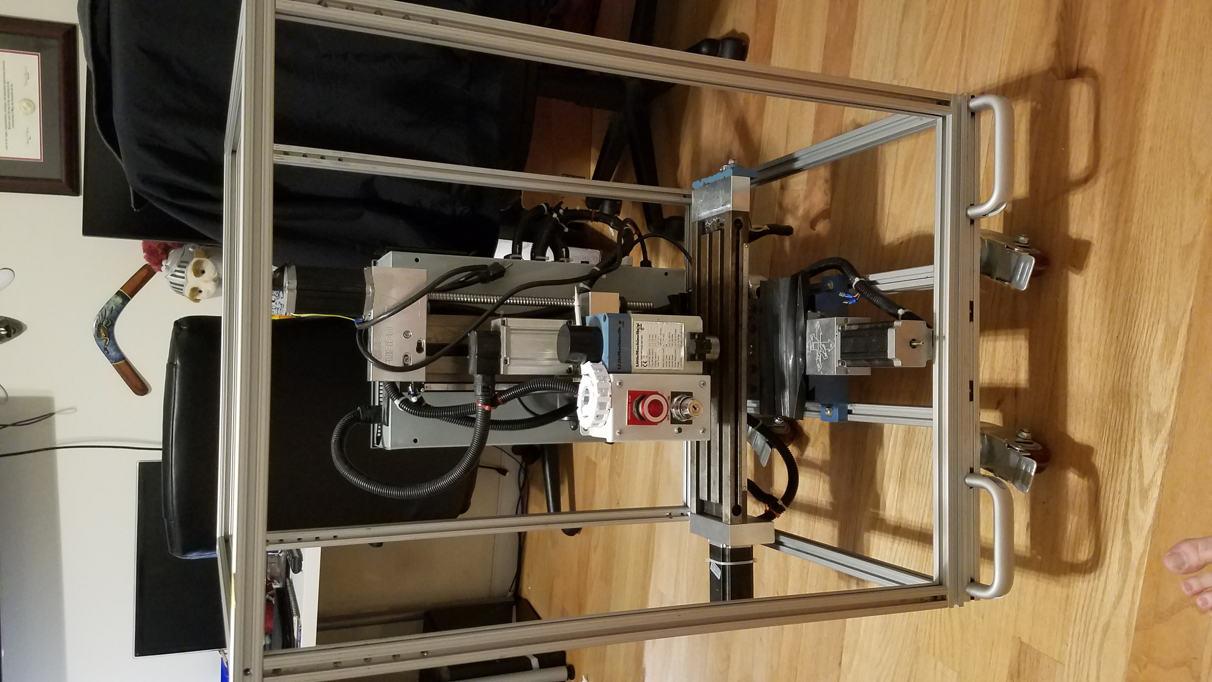
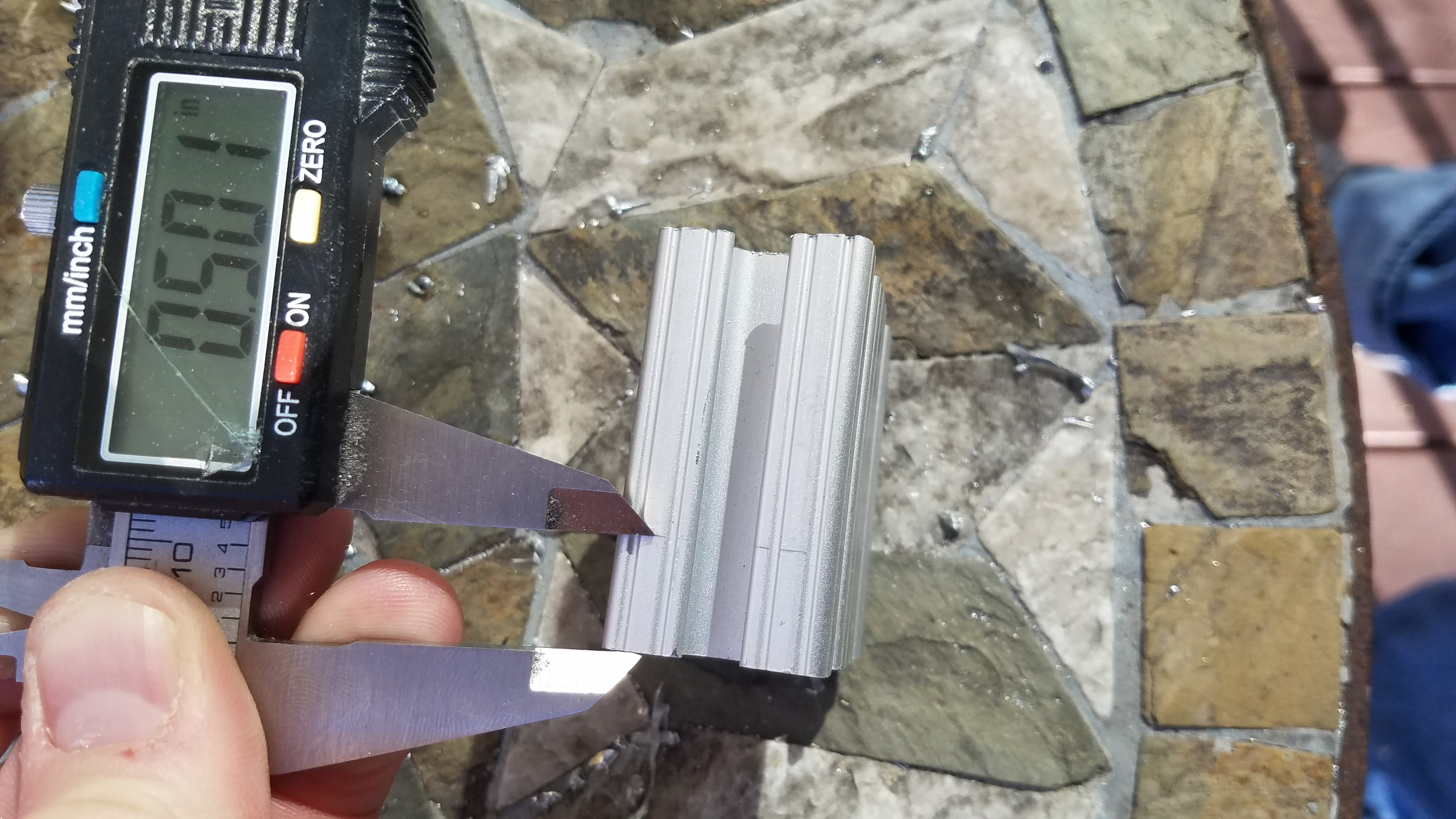
The types of Tslot used to build the frame. 1in x 1inx 24in and 1in x 2in x 24in. The frame X and Y dimensions are 24in x 26in. This dimesion was choosen to encompass the entire CNC while also requiring minimal cuts.
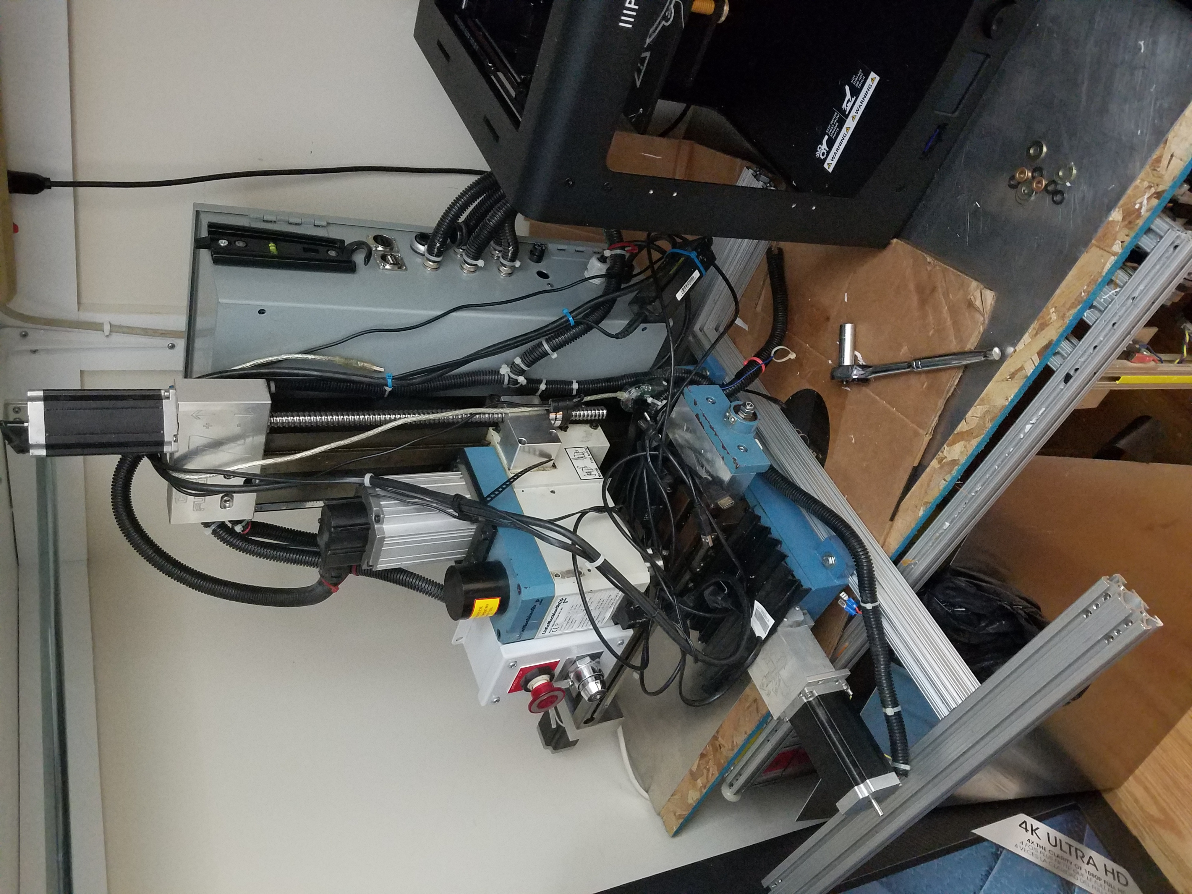
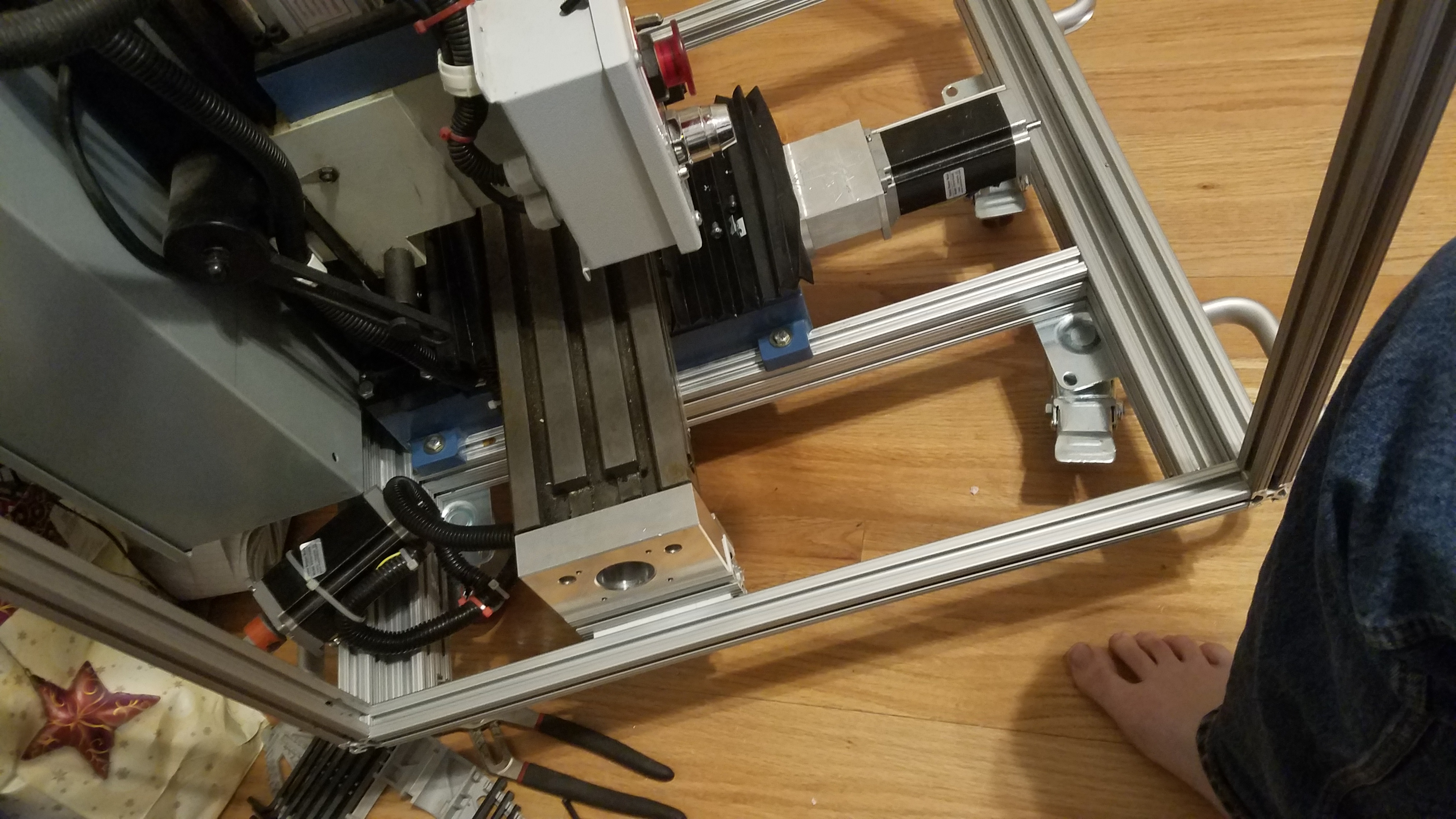
The CNC was bolted directly to the 1in x 2in x 24 rails. The 2in dimesion is vertical as to resist bending due to the weight of the CNC ~120lbs.
Top Enclosure Frame
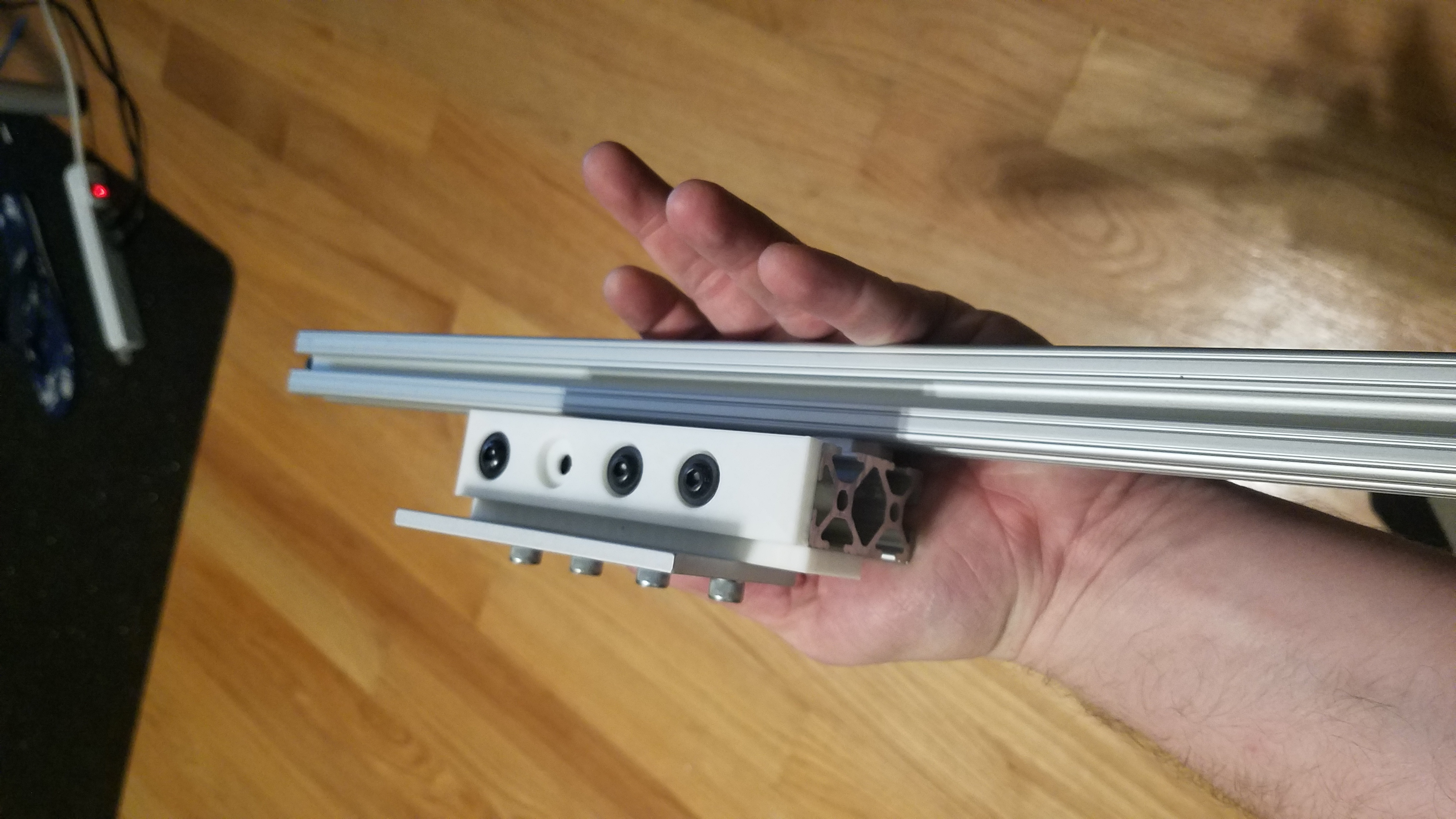
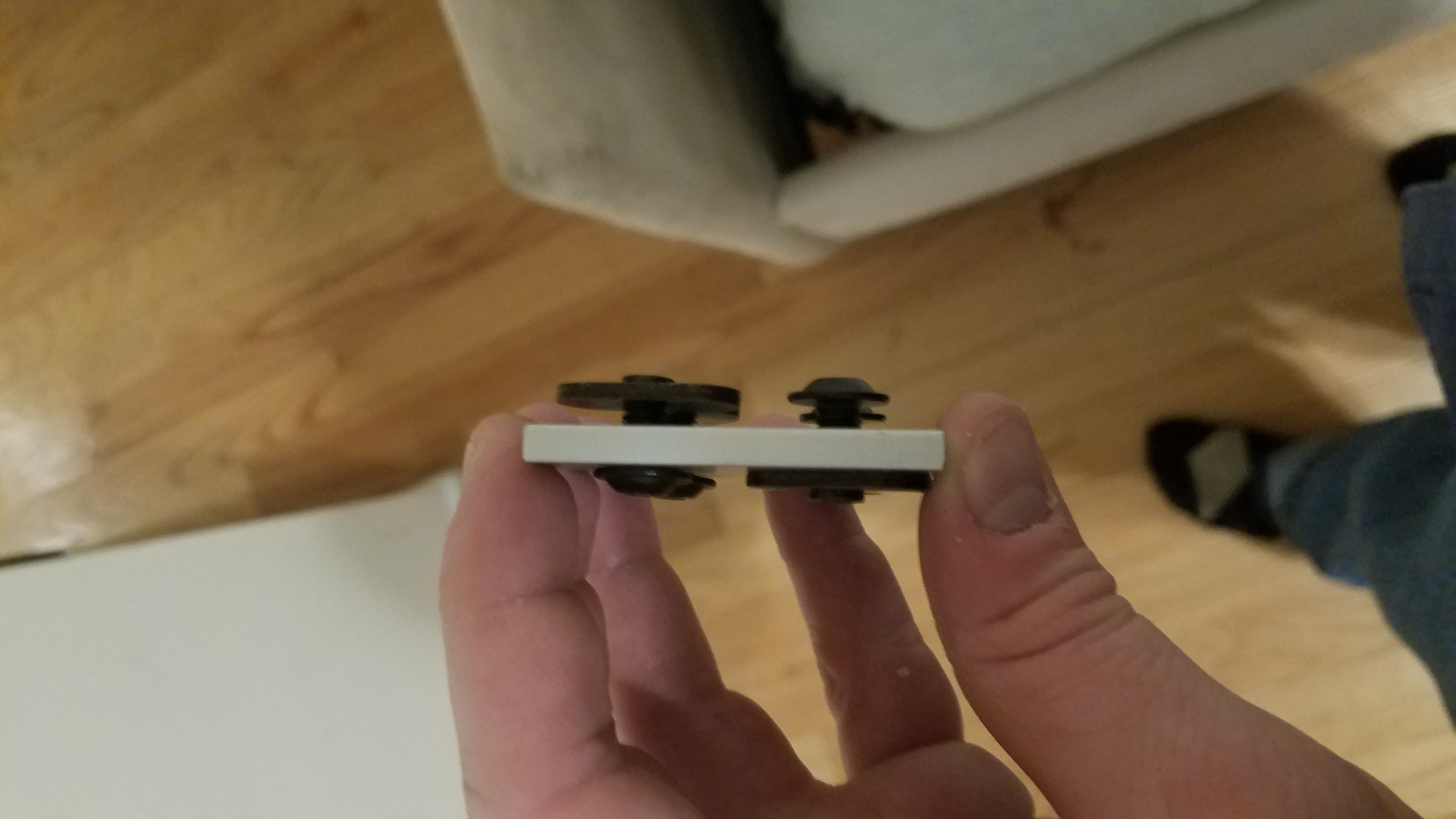
The top of the enclosure frame will slide with the X axis back and forth. This allows me to compress the size of the overall frame without losing the protection of a fully enclosed machine. This is a 3d printed 80/20 linear bearing. I printed this in PLA. With the addition of some greese it slides very easily even under load.
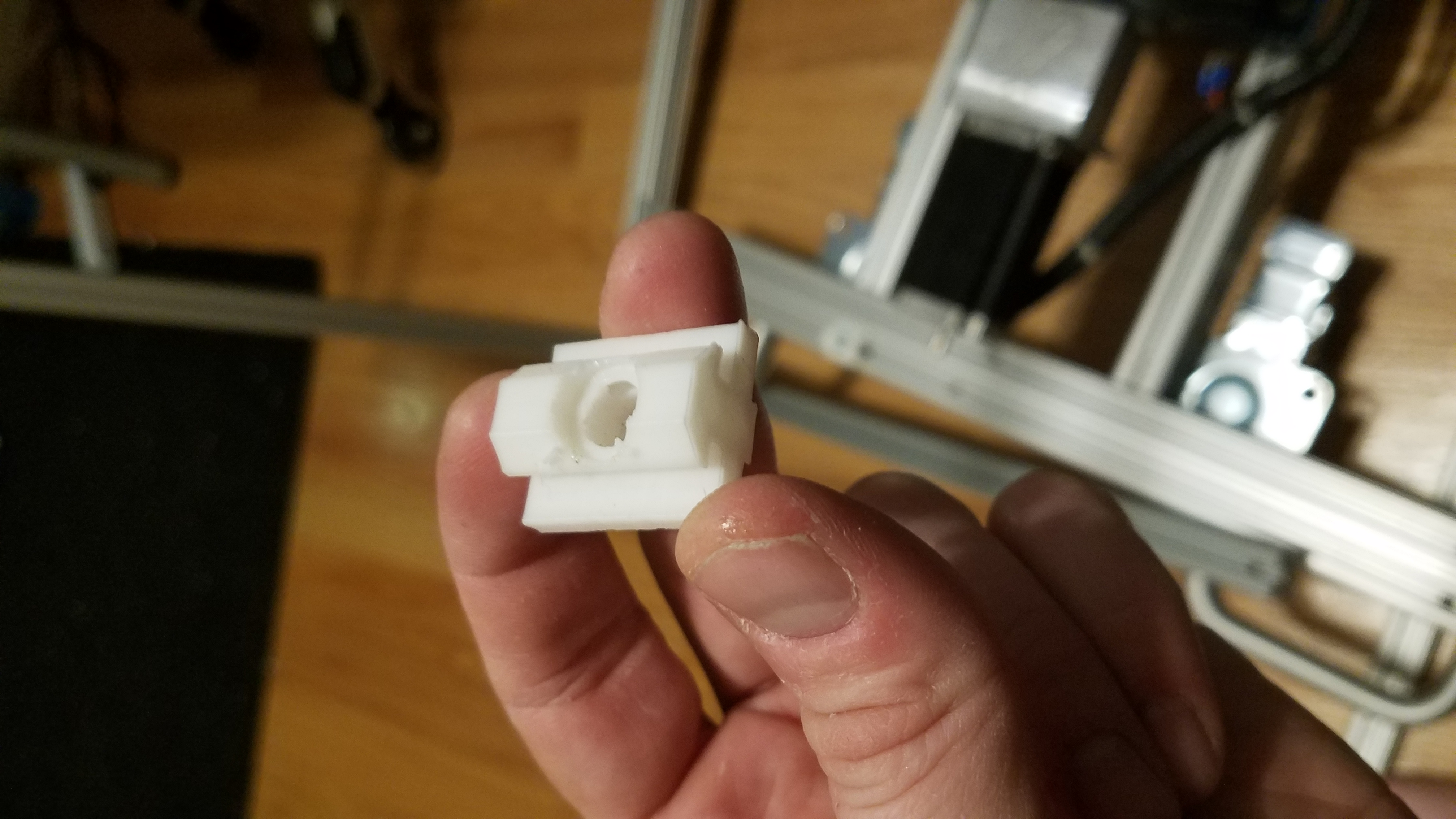
3D Printed 80-20 bearing.
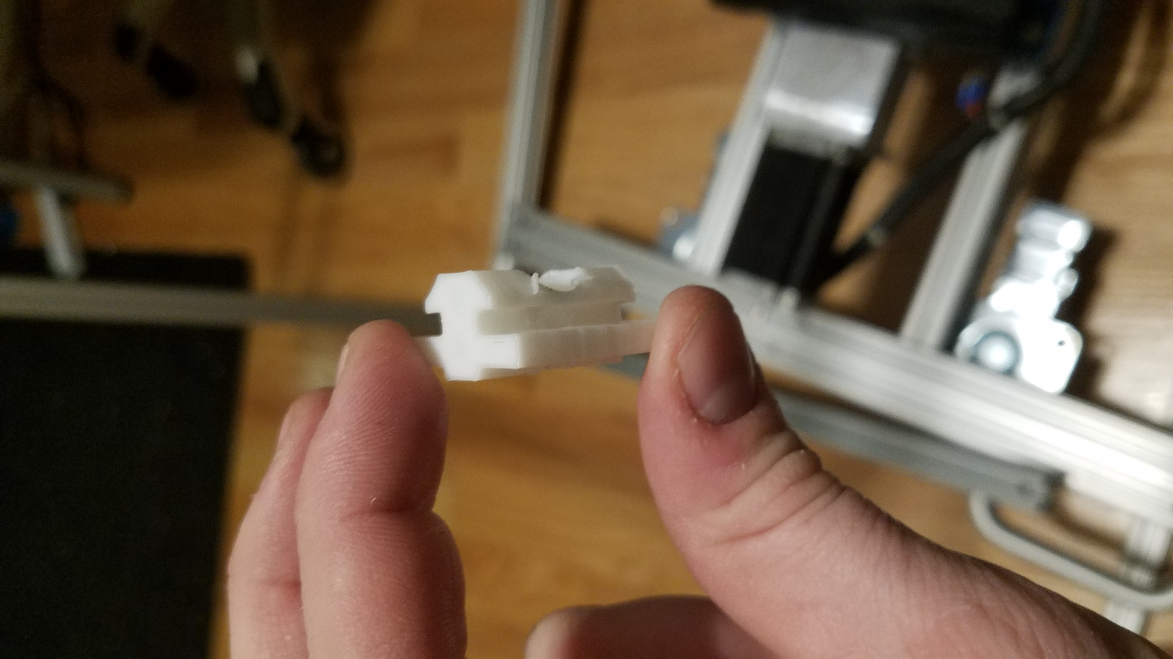
Profile shot of the 80-20 bearing
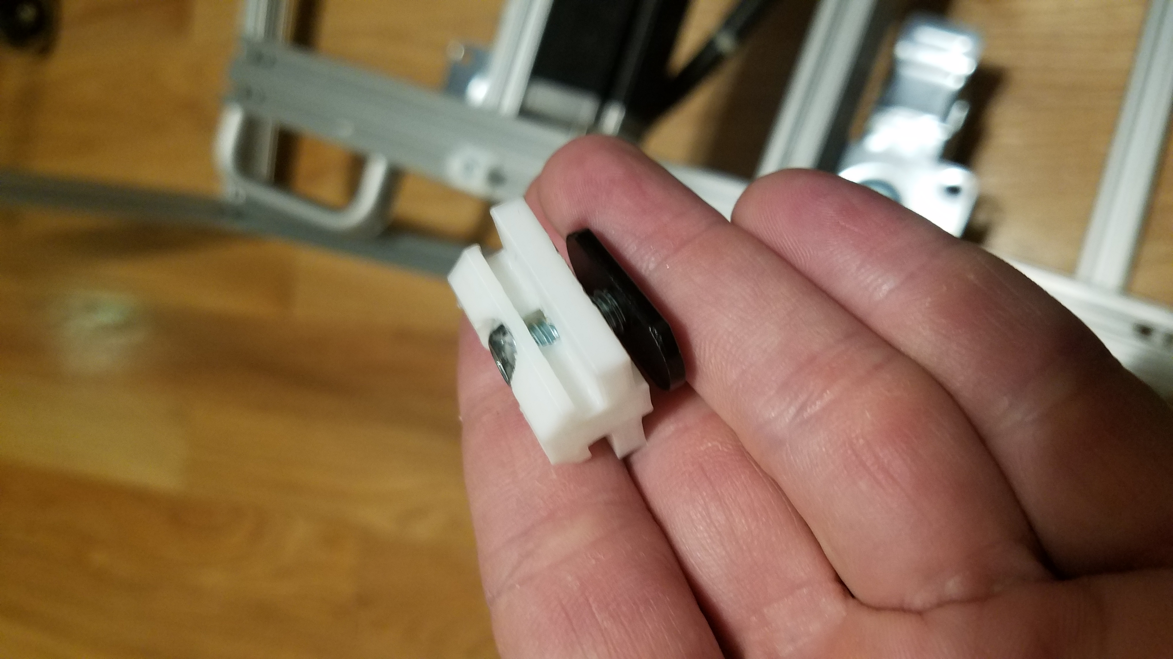
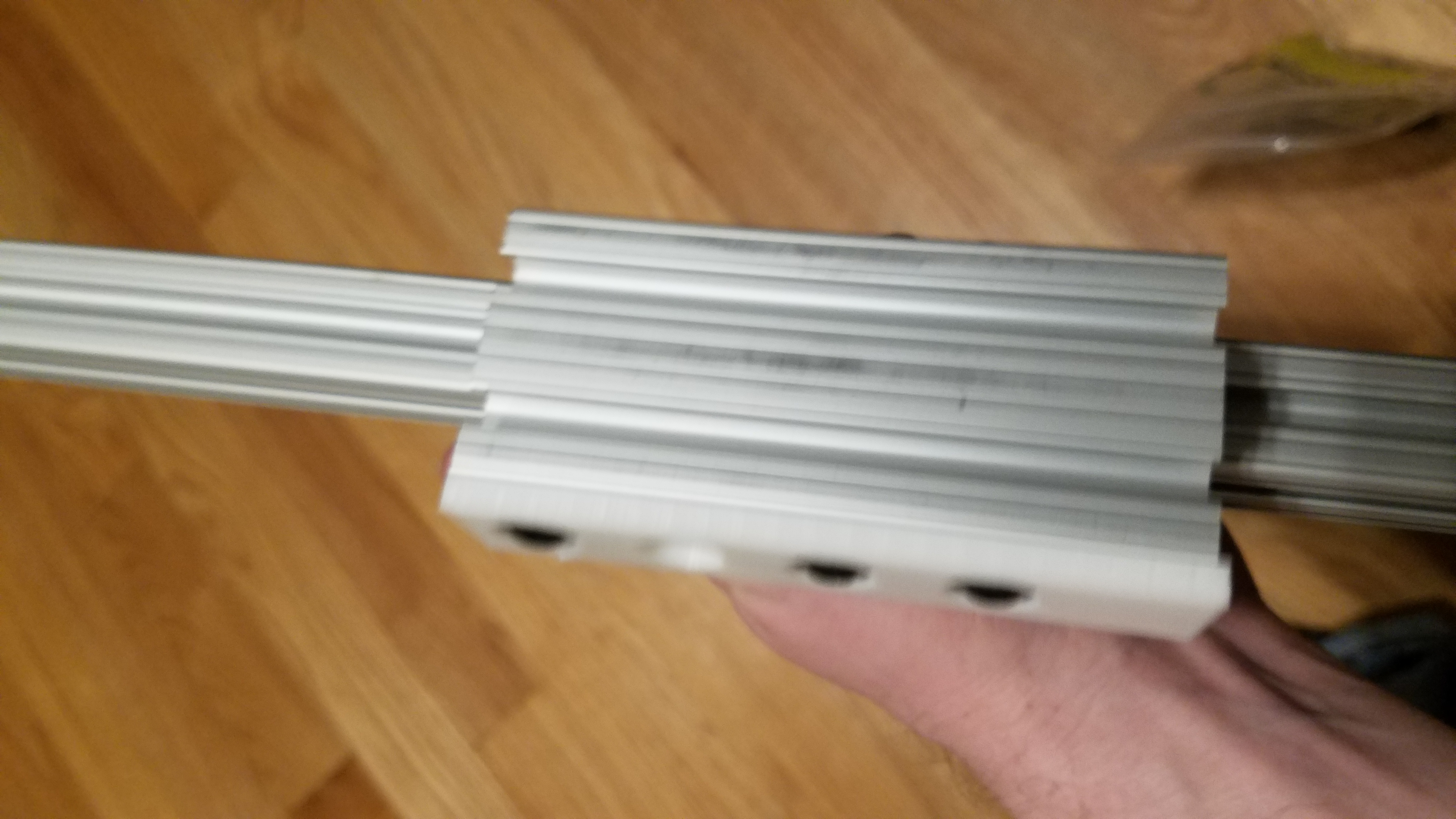
3d printed 80-20 bearing with a screw and tslot nut.
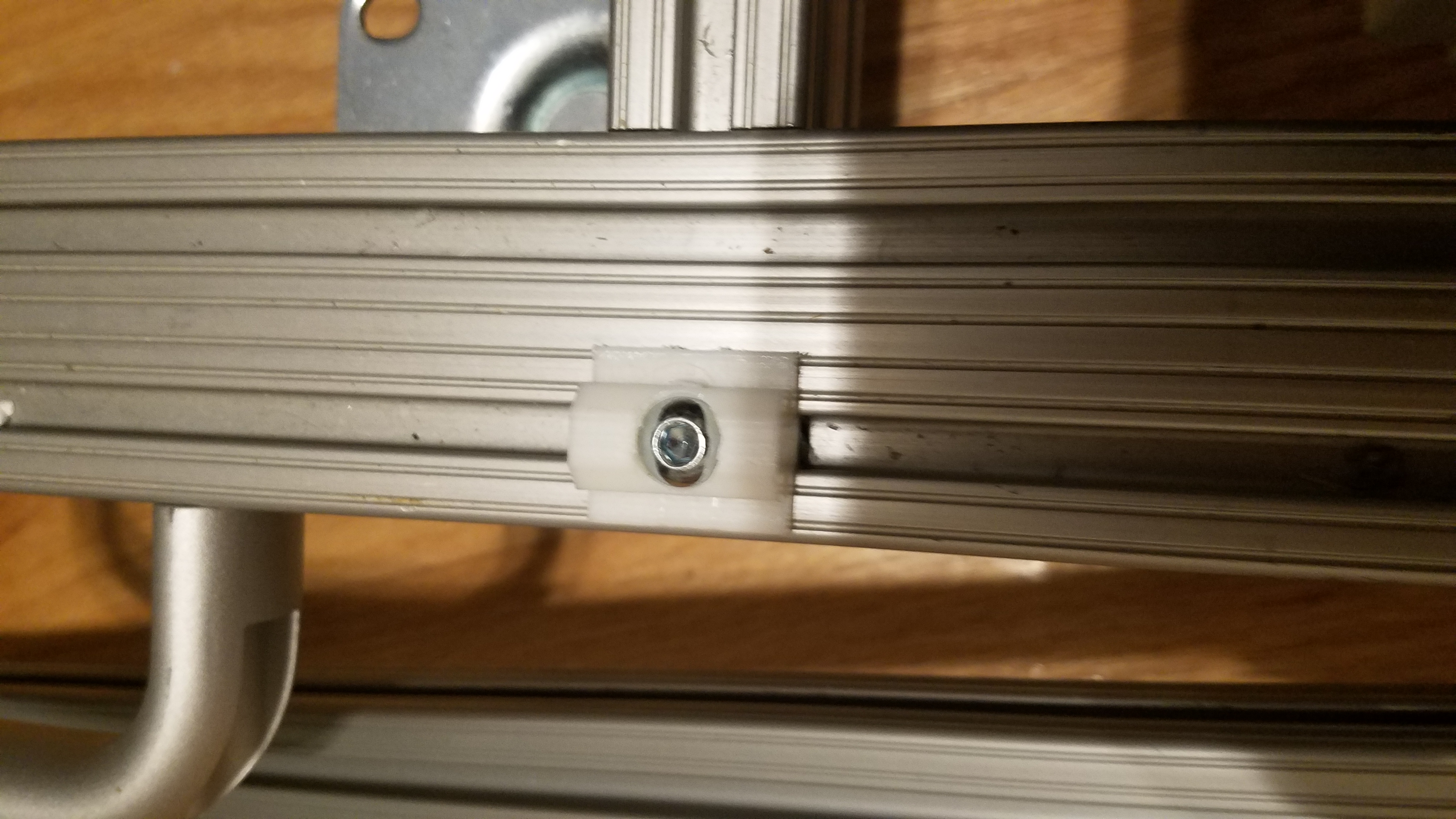
3d printed 80-20 bearing mounted on the base.
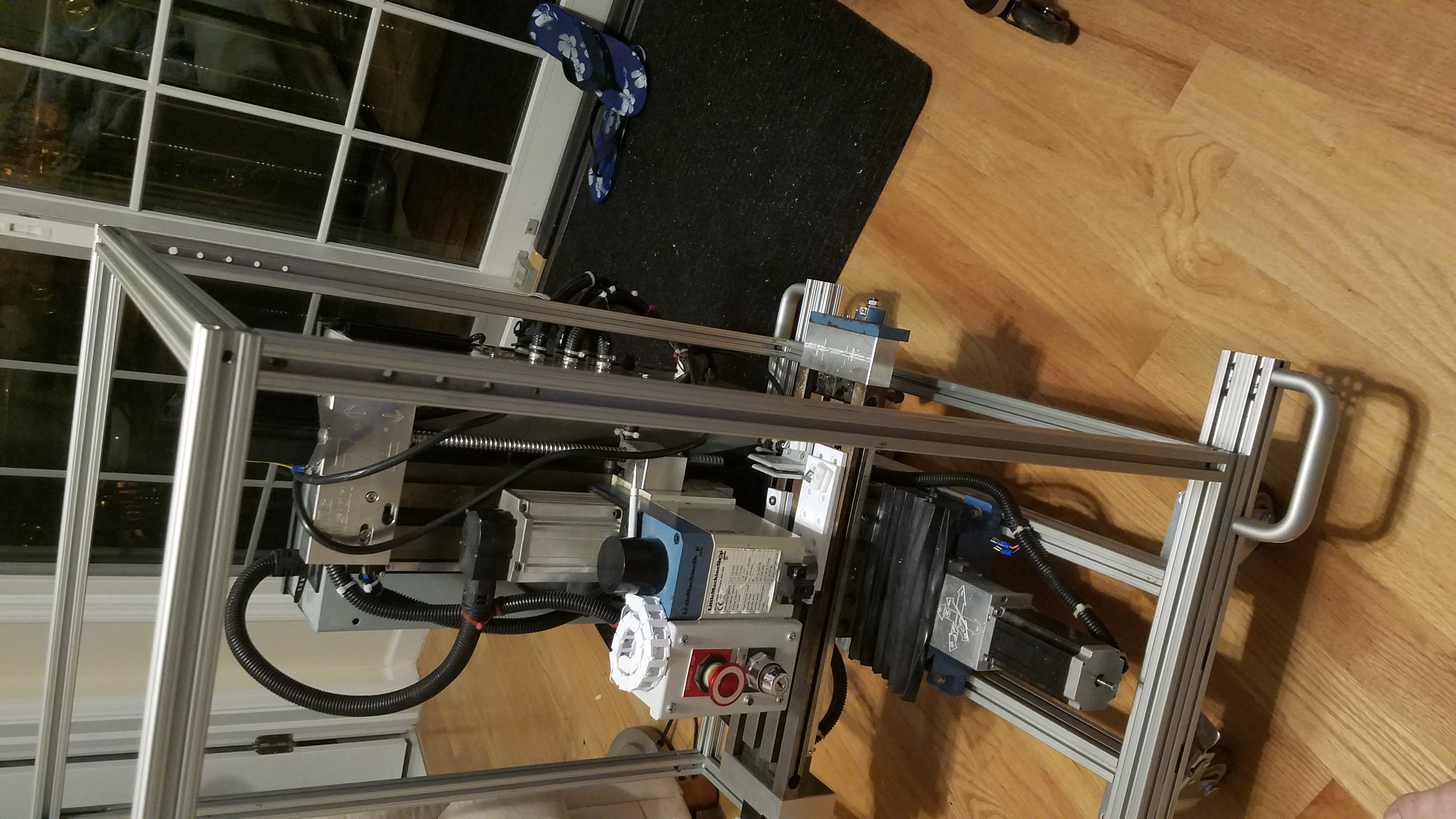
The bottom rail of the top enclosure will slide on these 80-20 bearings. The X/Y table of the CNC will be connected to the Top enclosure. This will shift the frame along with the Y axis. The axis of the CNC table will move inside the top enclosure.
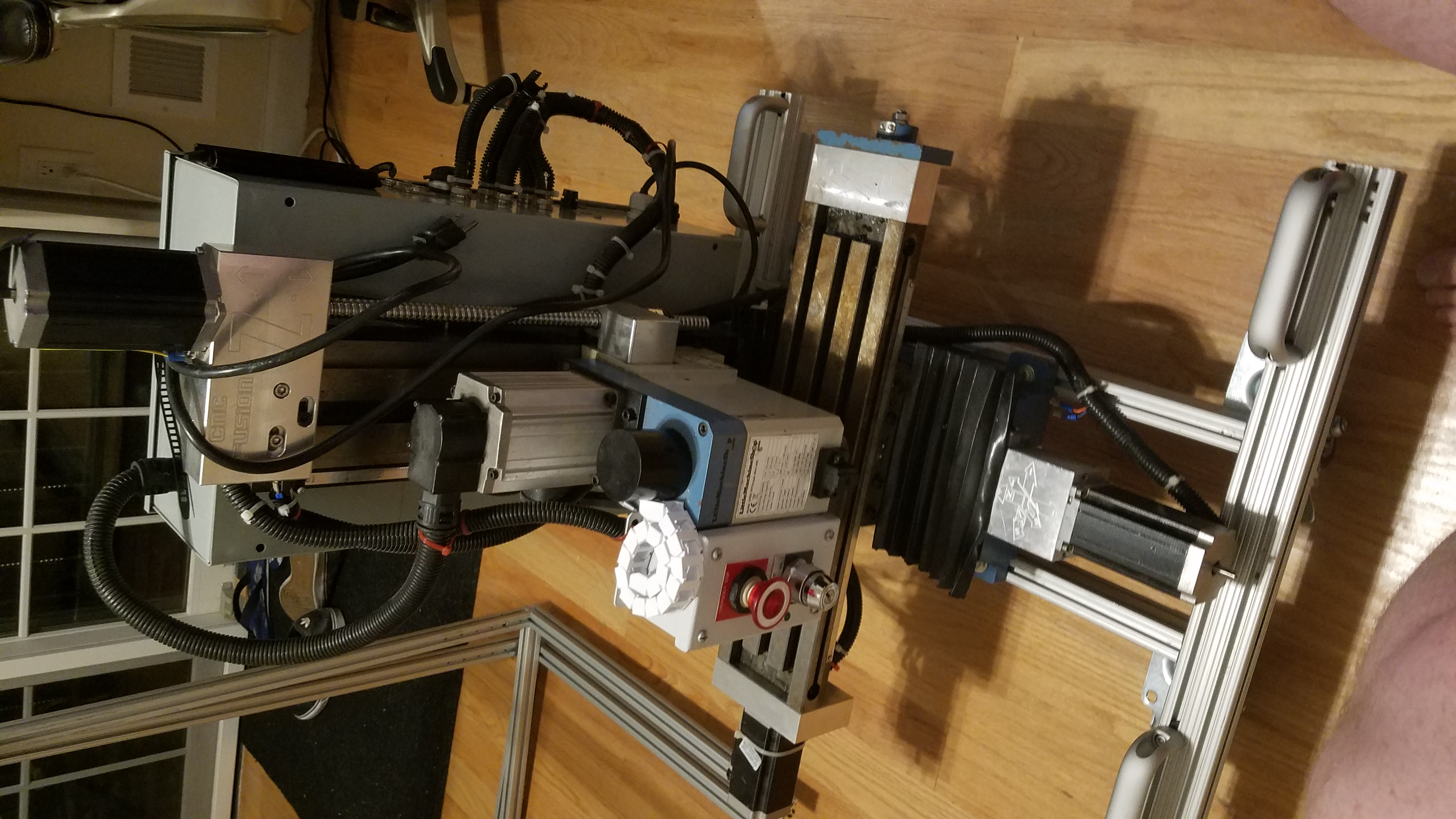
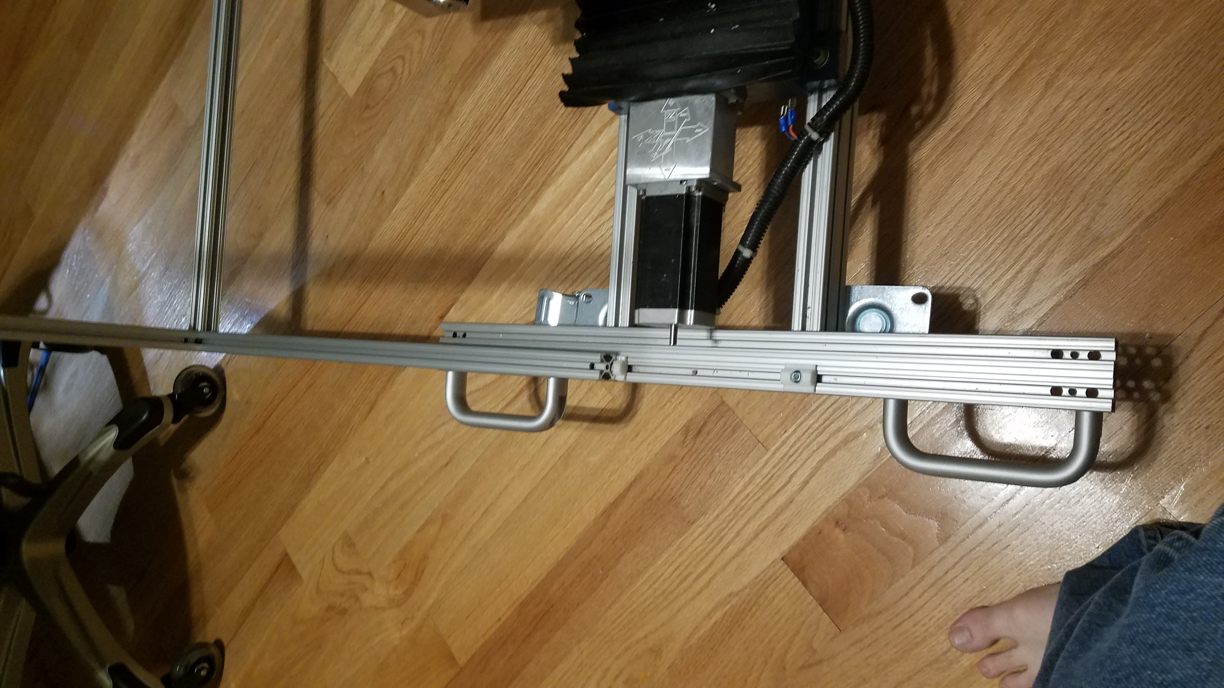
View of the top frame before connecting the X axis to the enclosure
Shifting the top enclosure to on side.
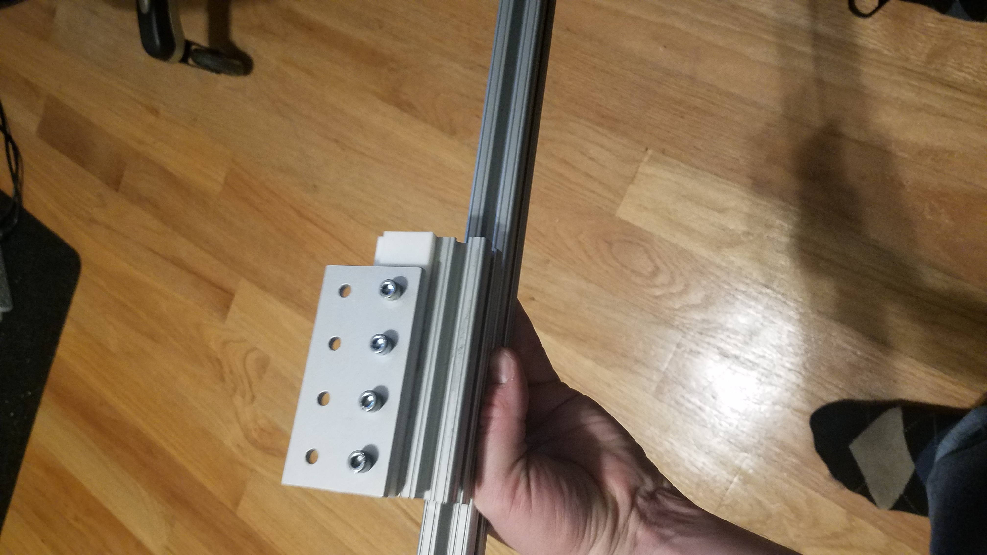
X/Y Table to Top Enclosure connection
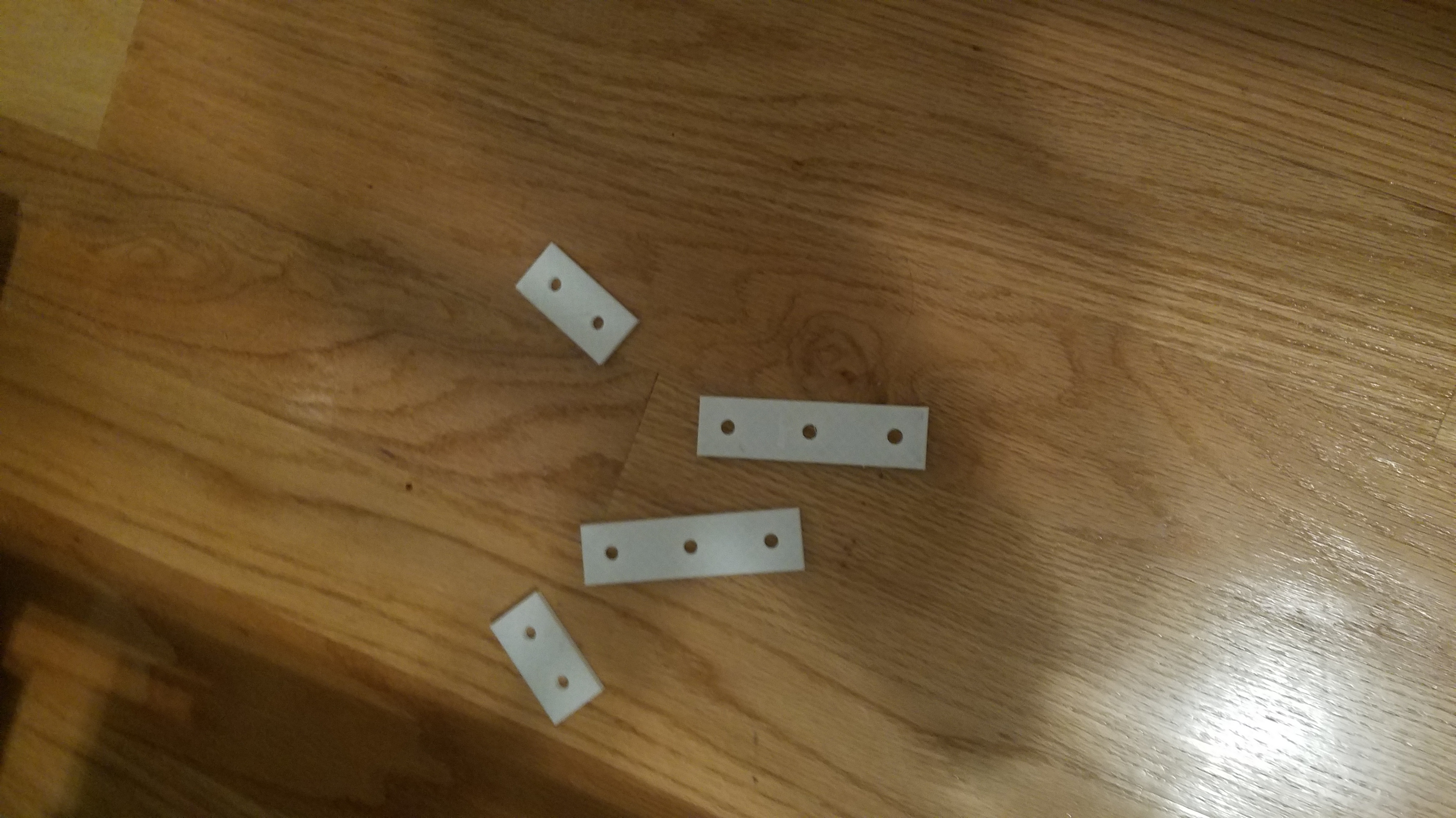
3D Printed connections and spacers.
Tslot and Tslot brackets that will connect the X/Y table to the Top Enclosure Frame.
Motor side
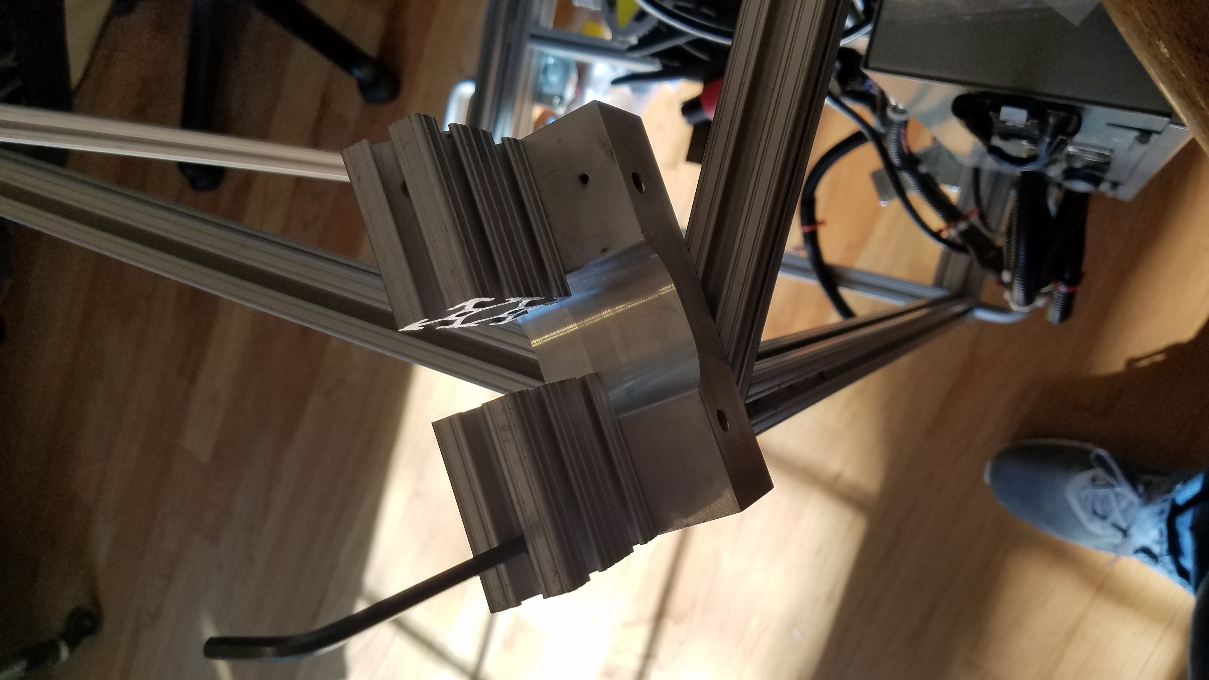
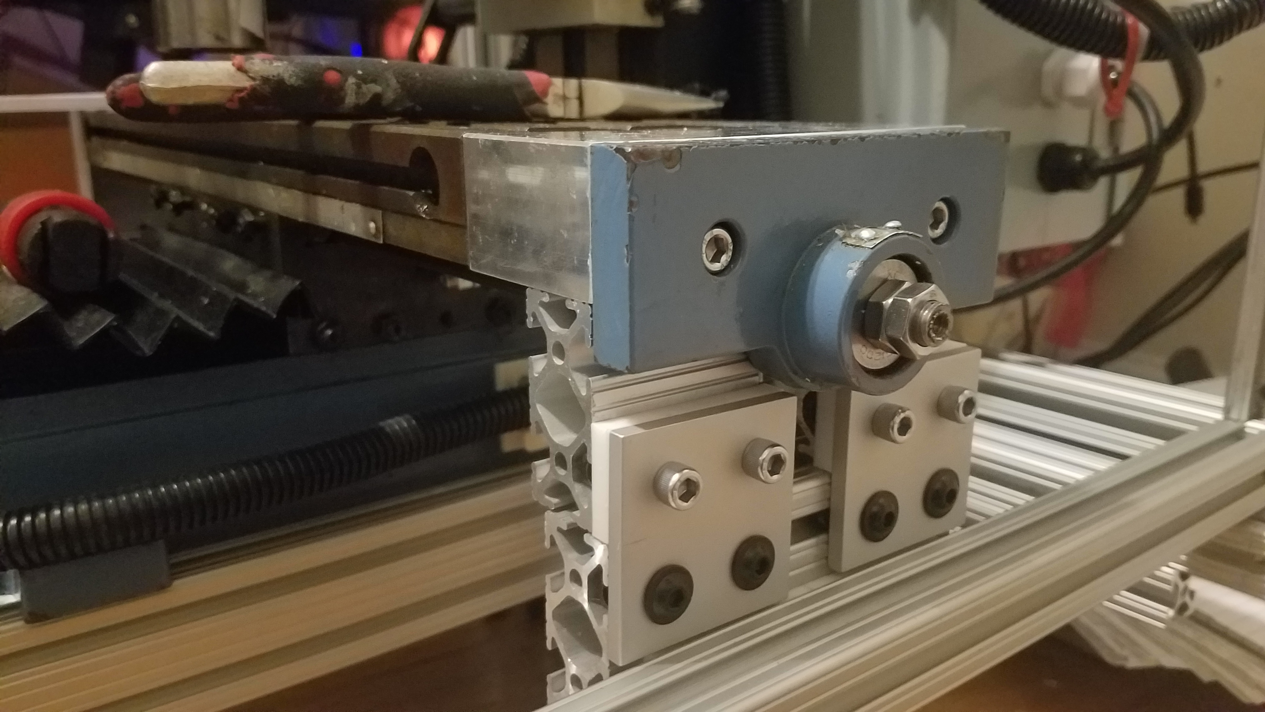
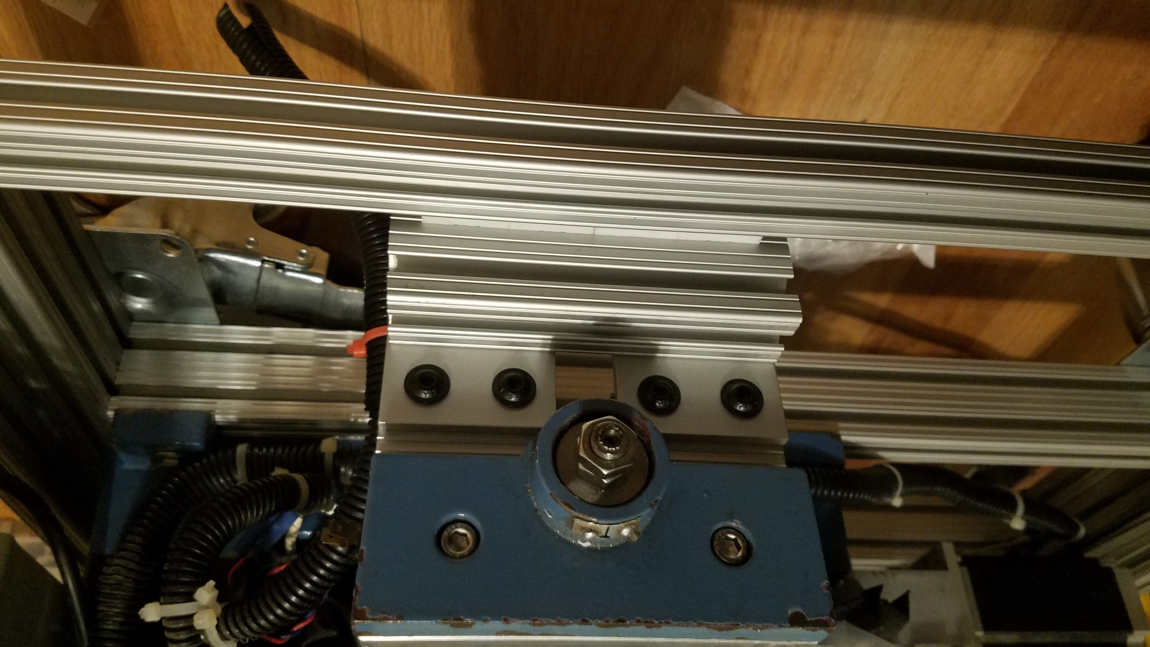
Top view of the X/Y table to Top Enclosure connection.
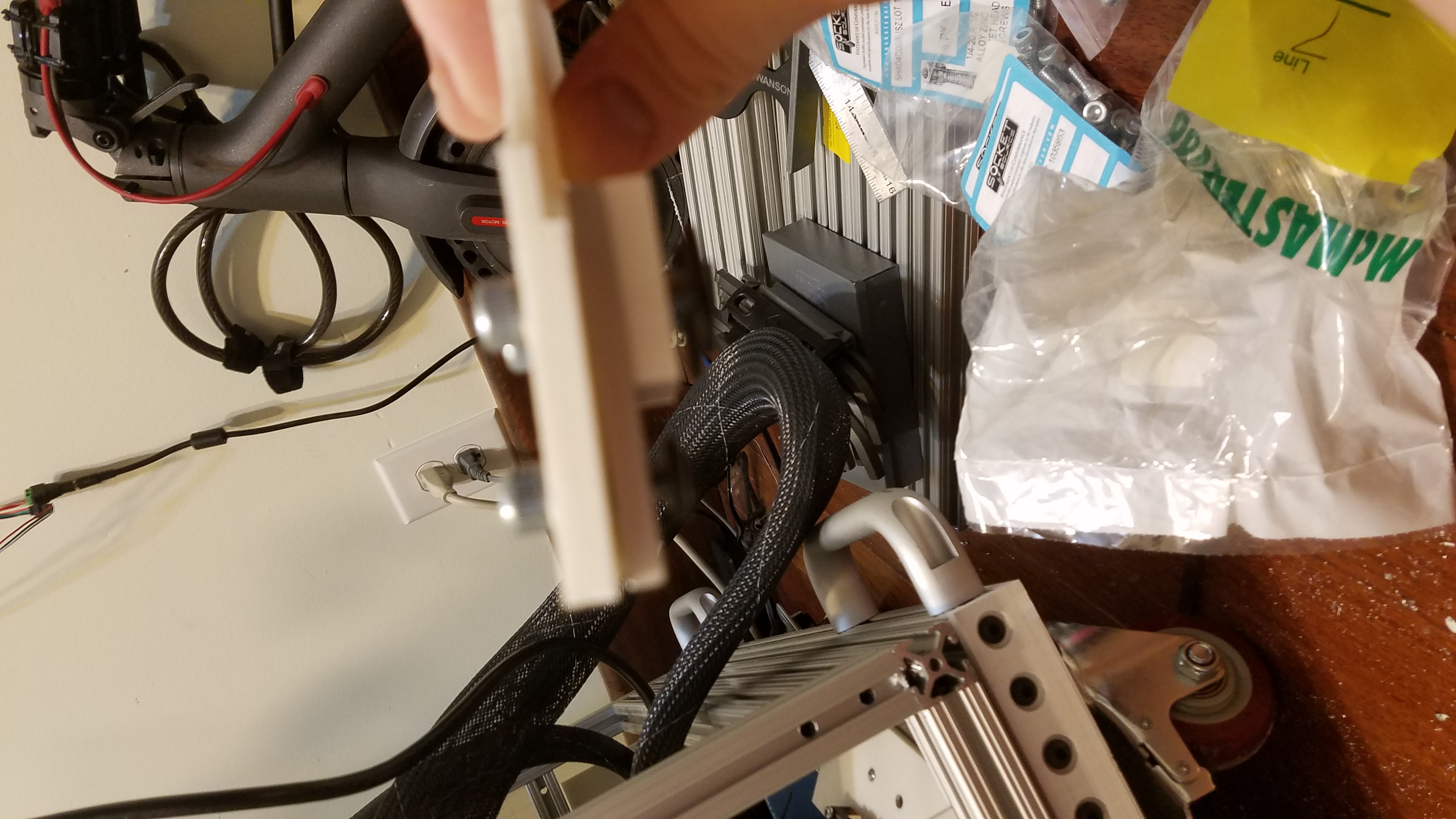
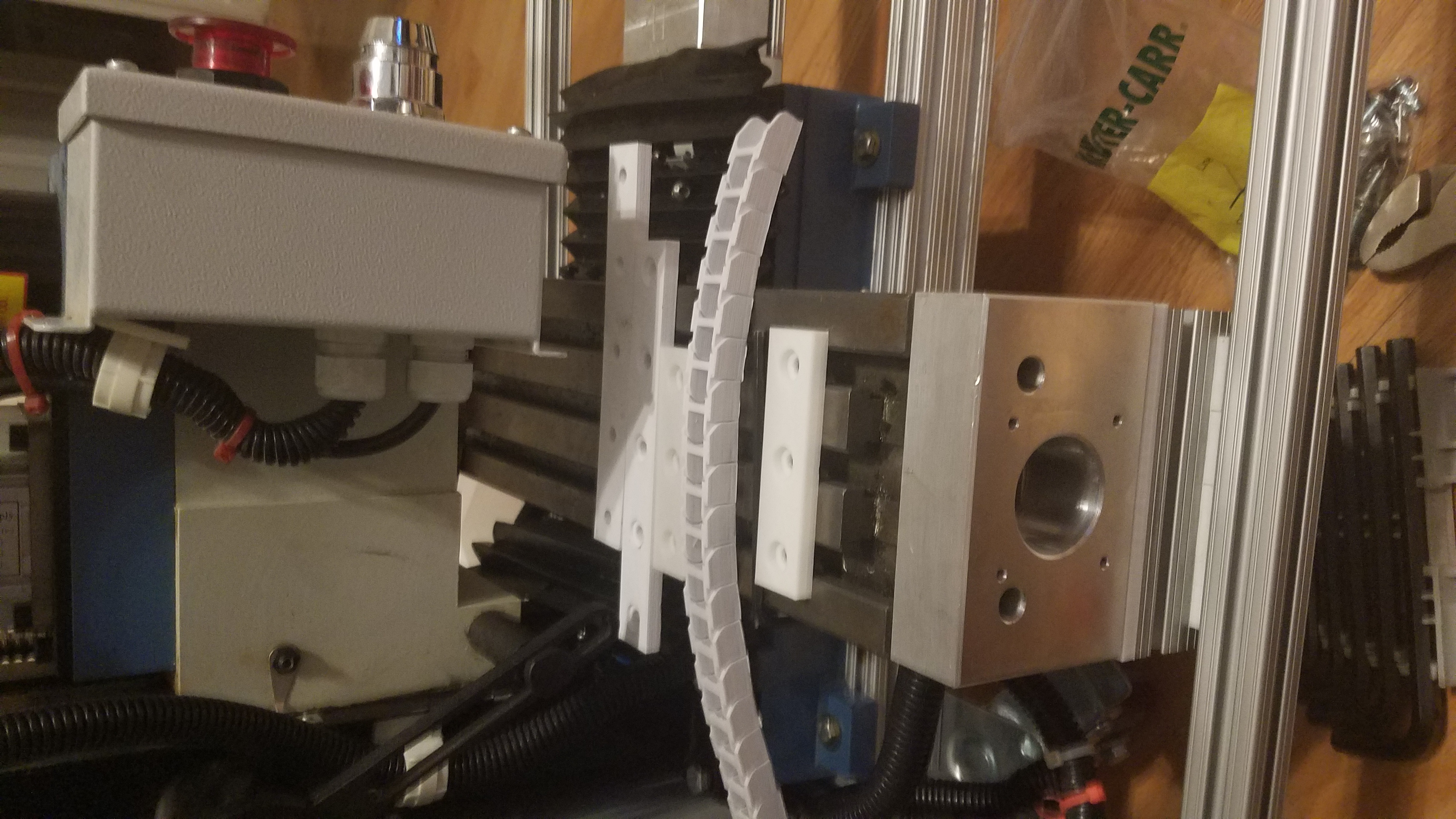
A close-up shot of an aluminum profile with a sliding component. It seems to show the assembly of one of the axes, using standard T-slot extrusion for mounting and moving components.
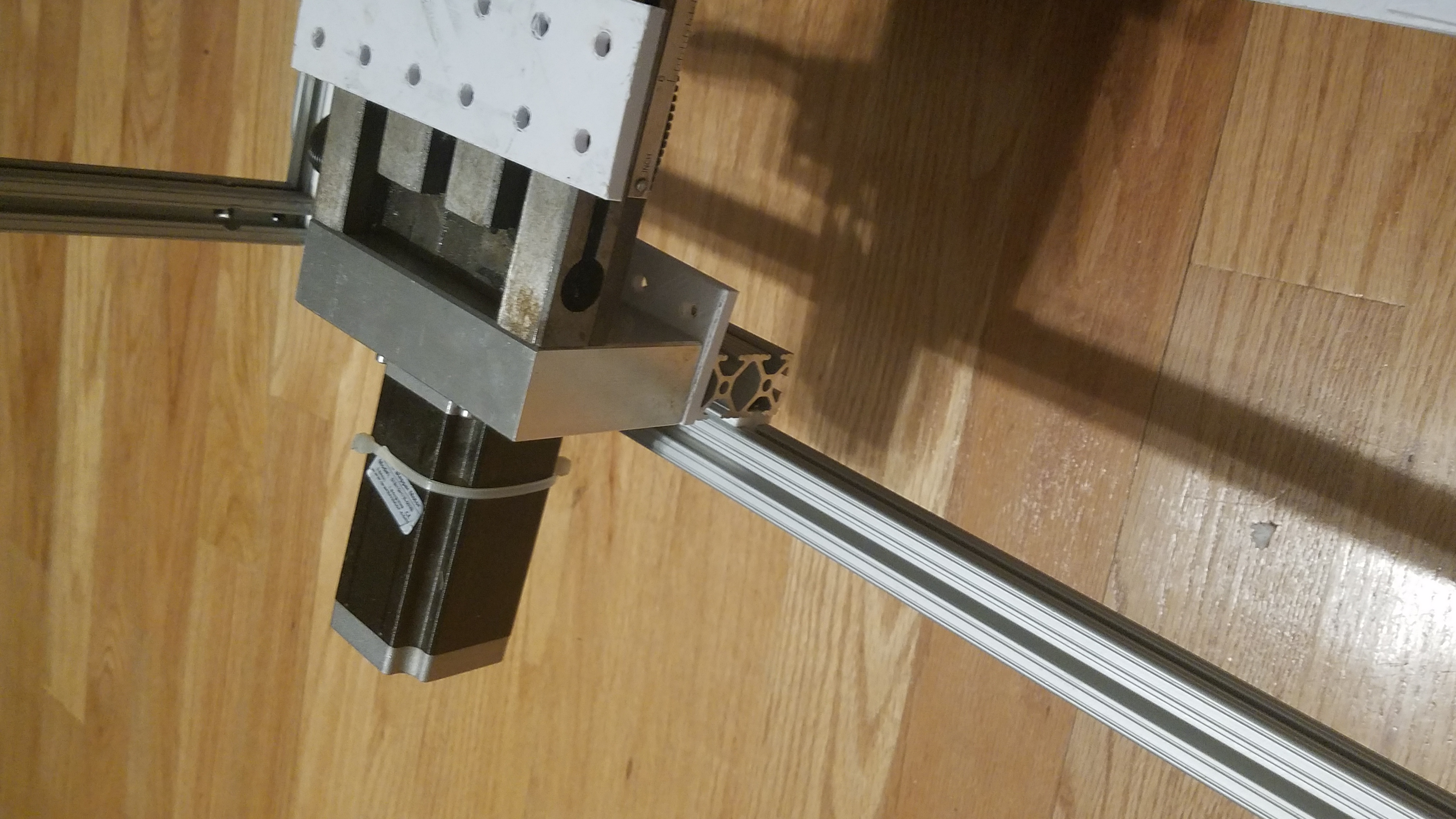
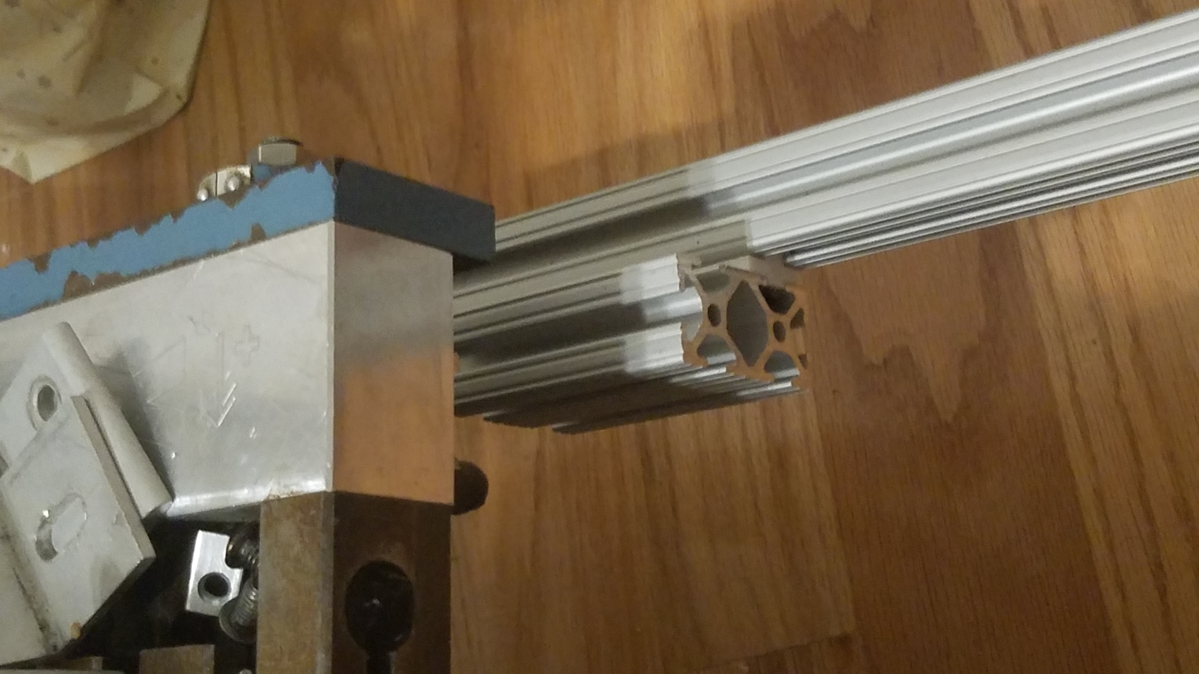
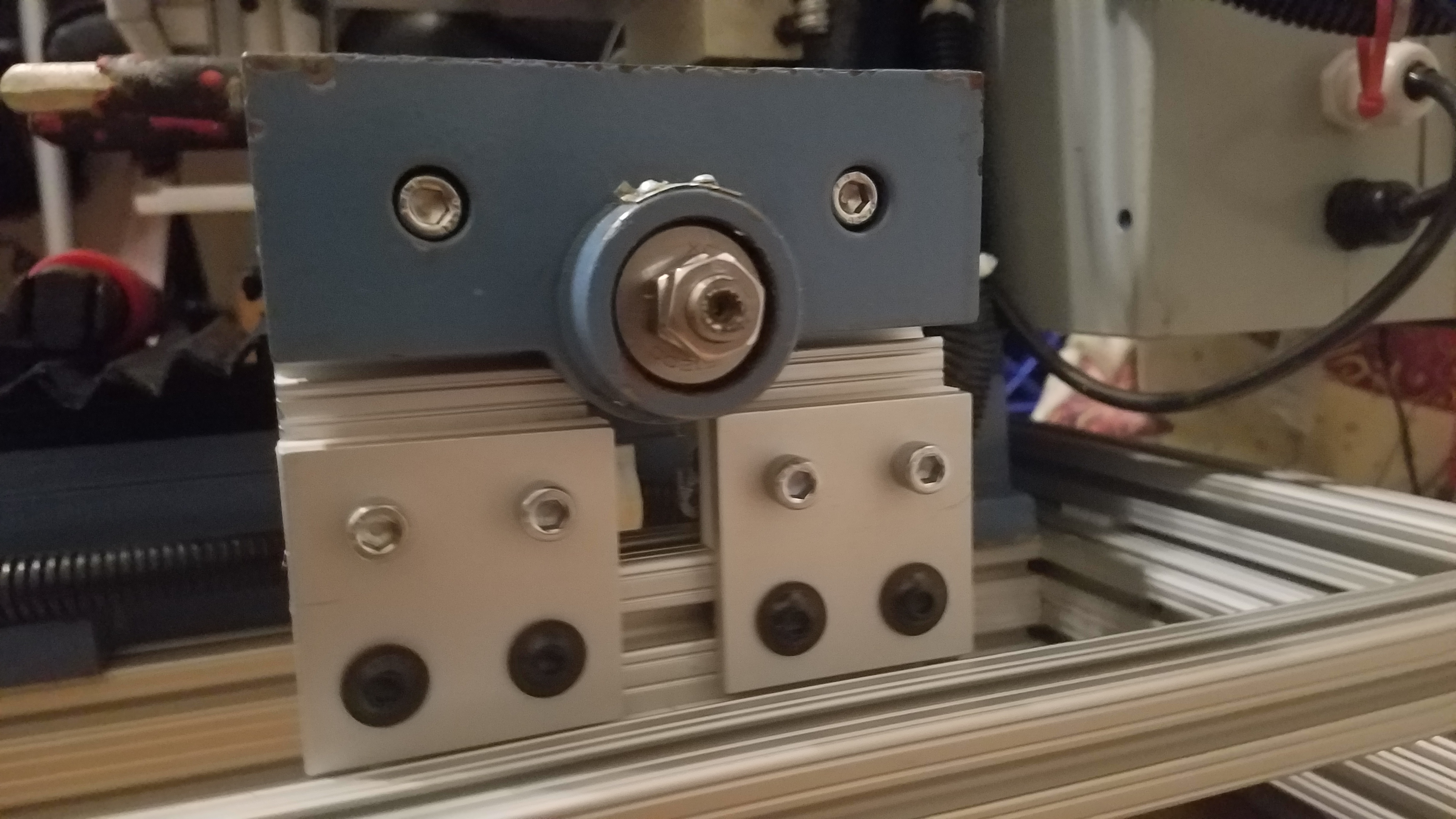
Side view of the X/Y table to Top Enclosure slide connection.
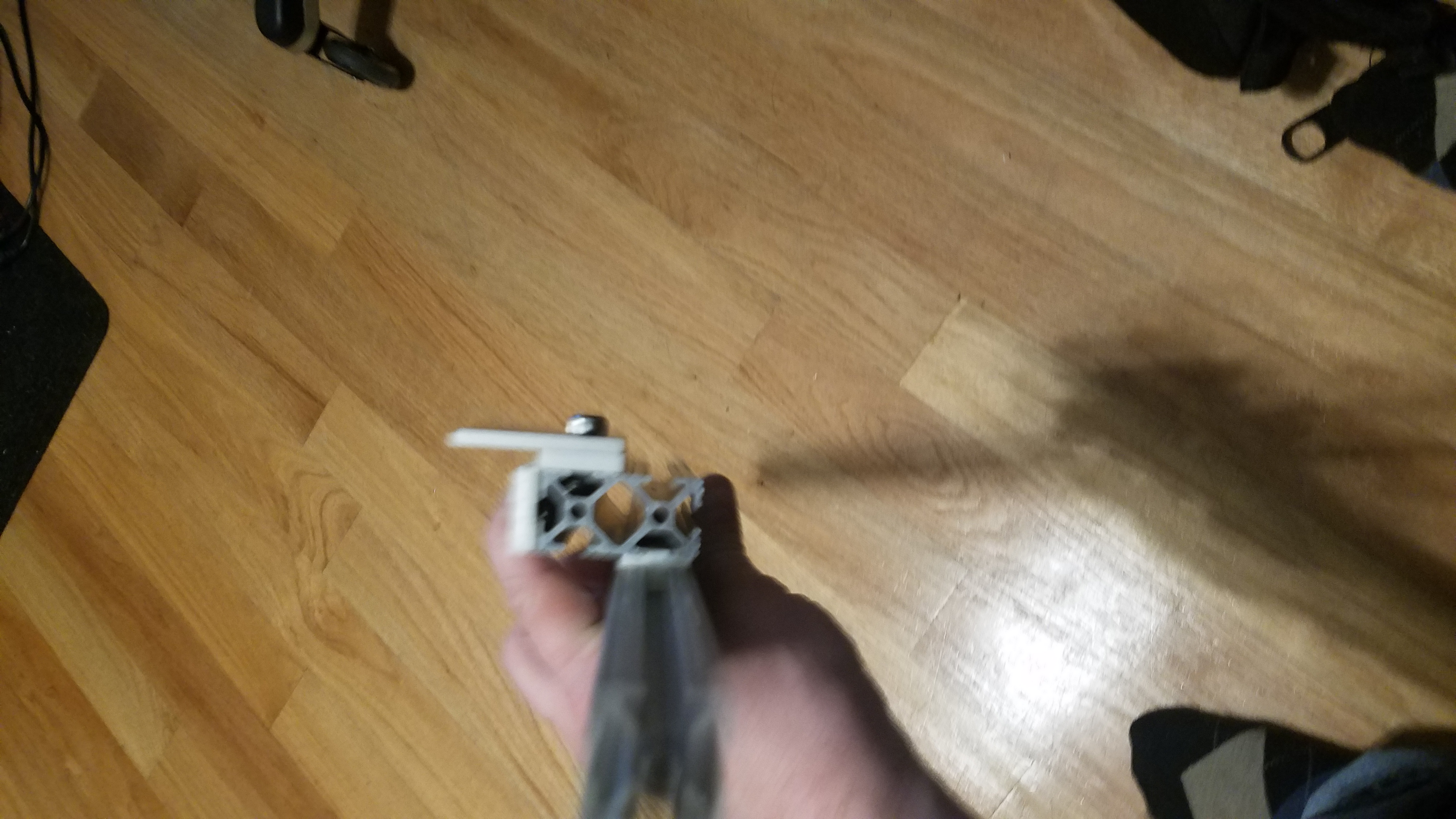
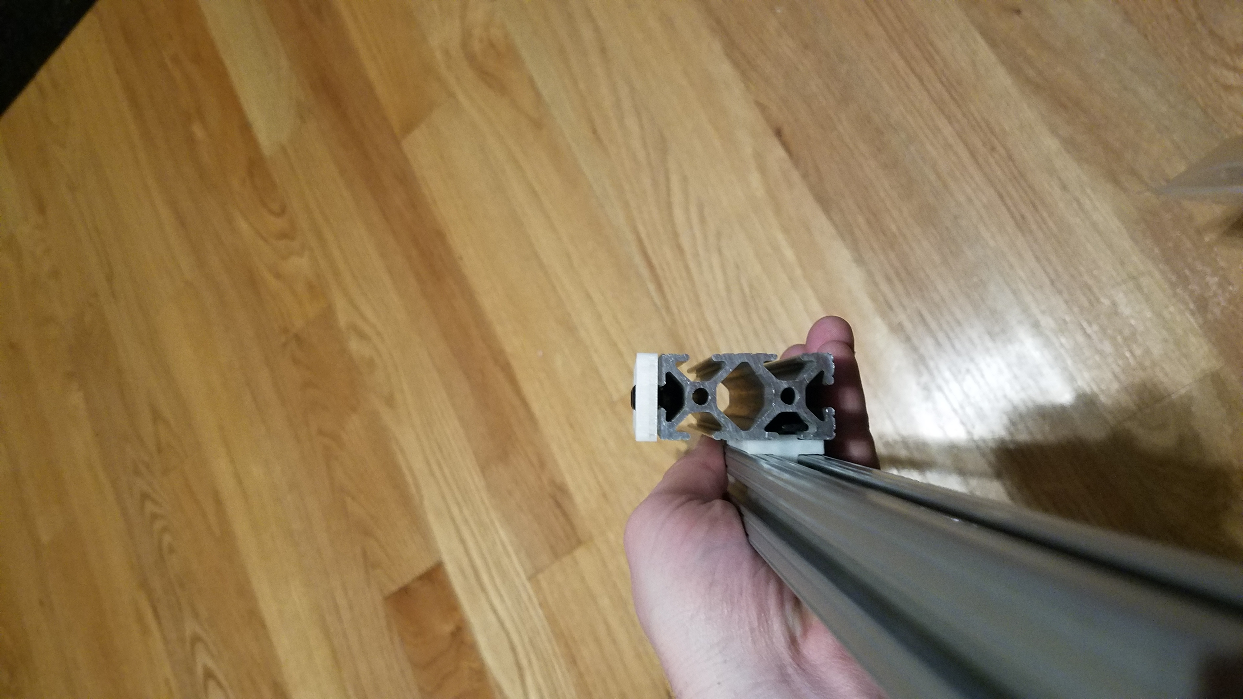
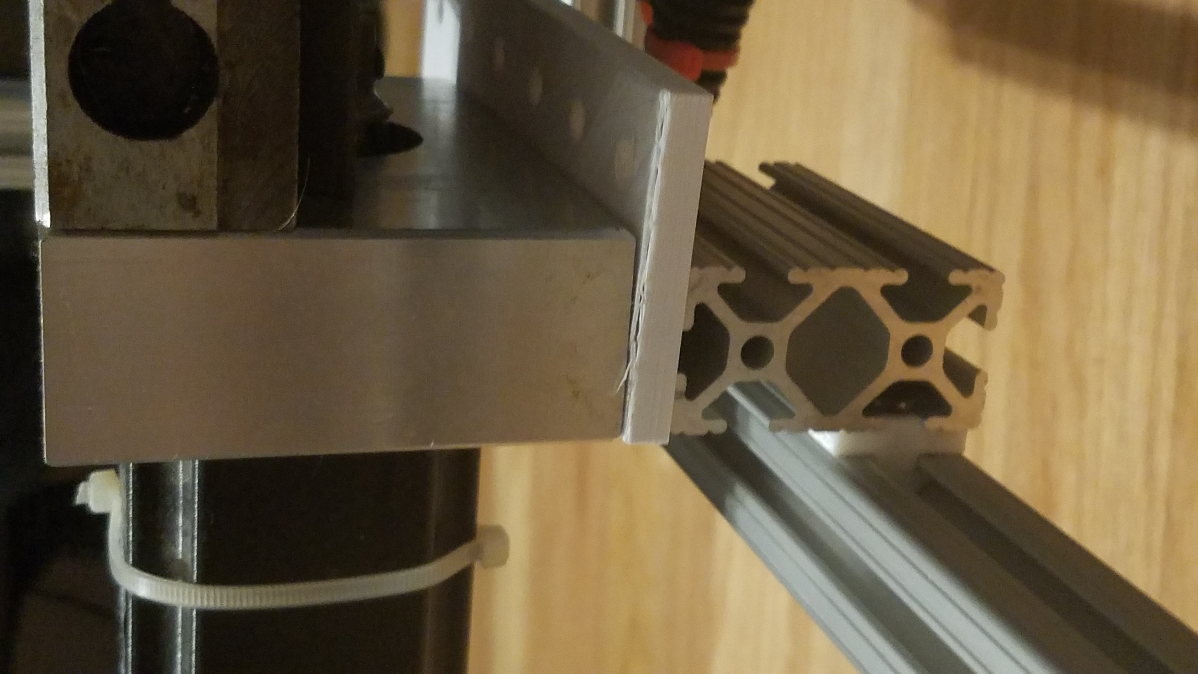
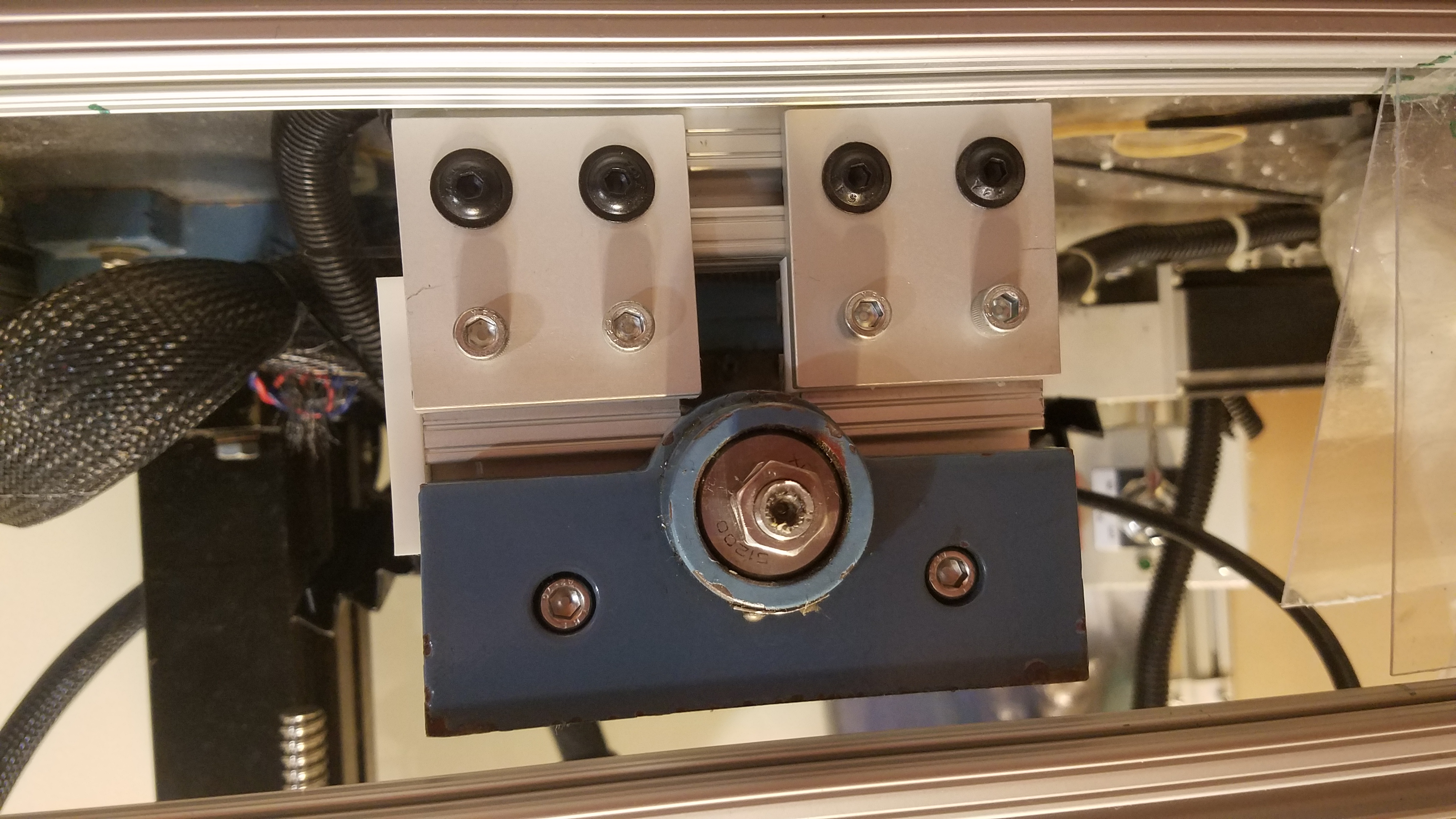
End view of the X/Y table to Top Enclosure slide connection. The 80-20 bearing is clearly seen in the Tslot. The Tslot rail is part of the Top Enclosure.
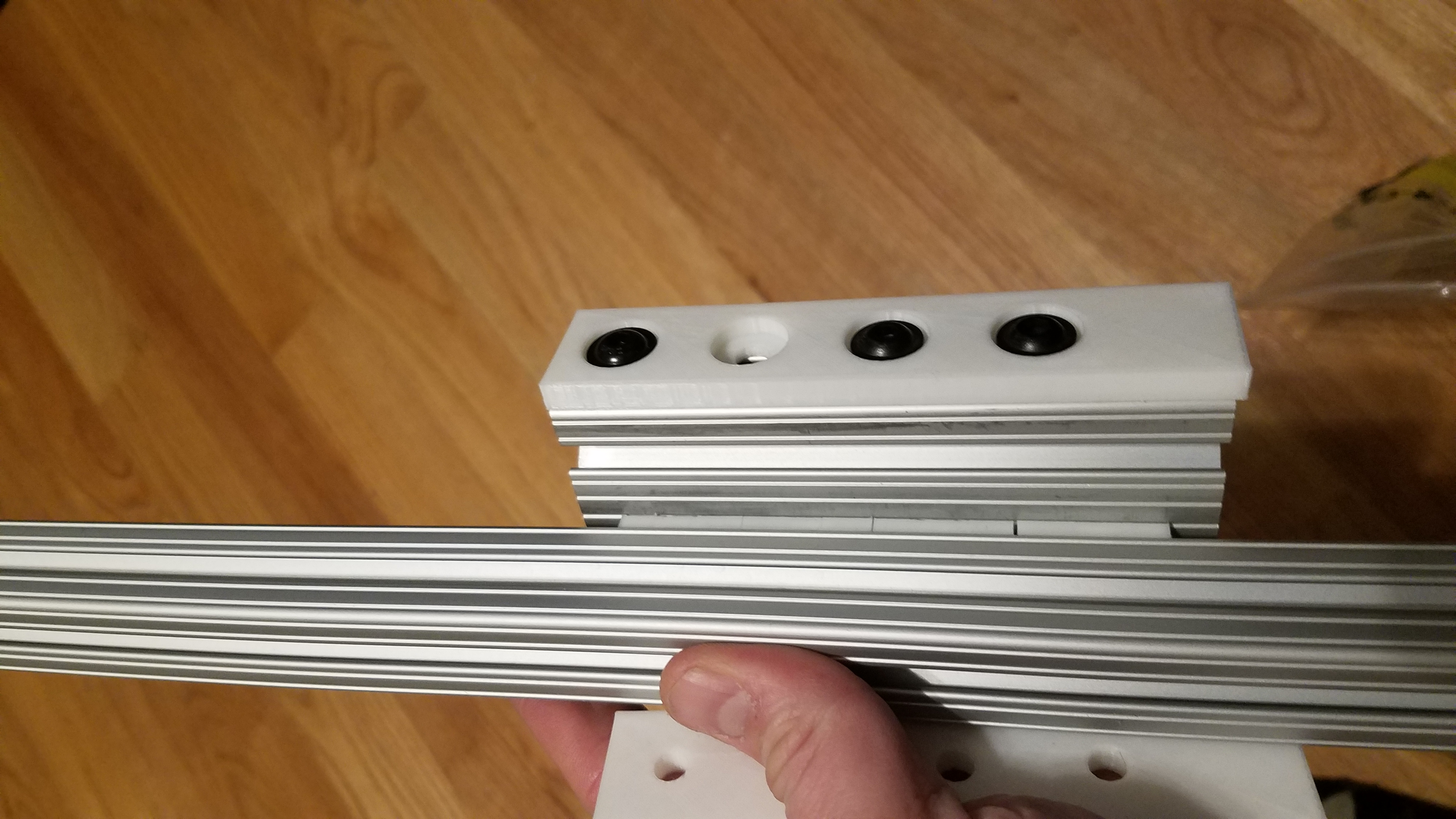
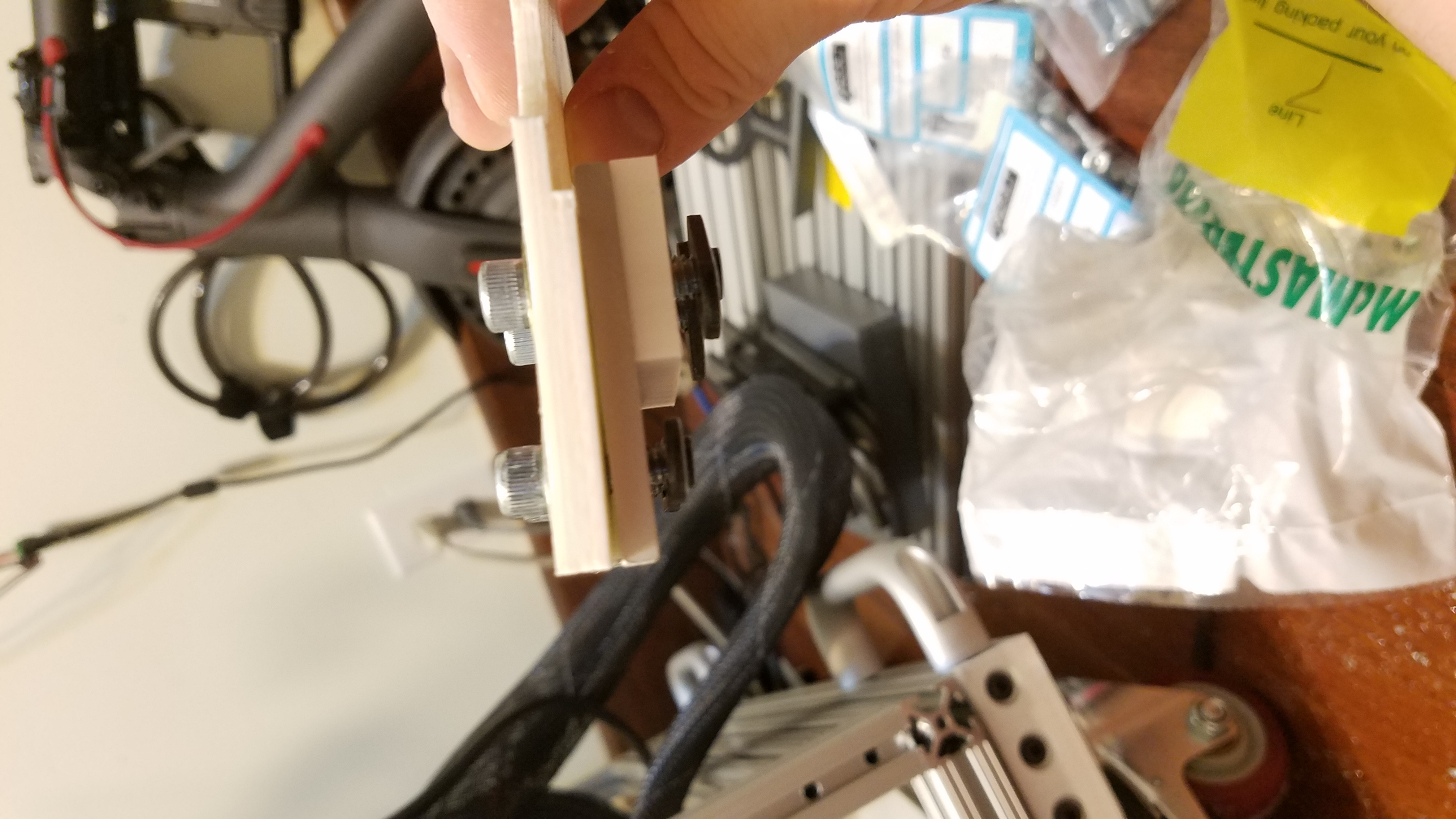
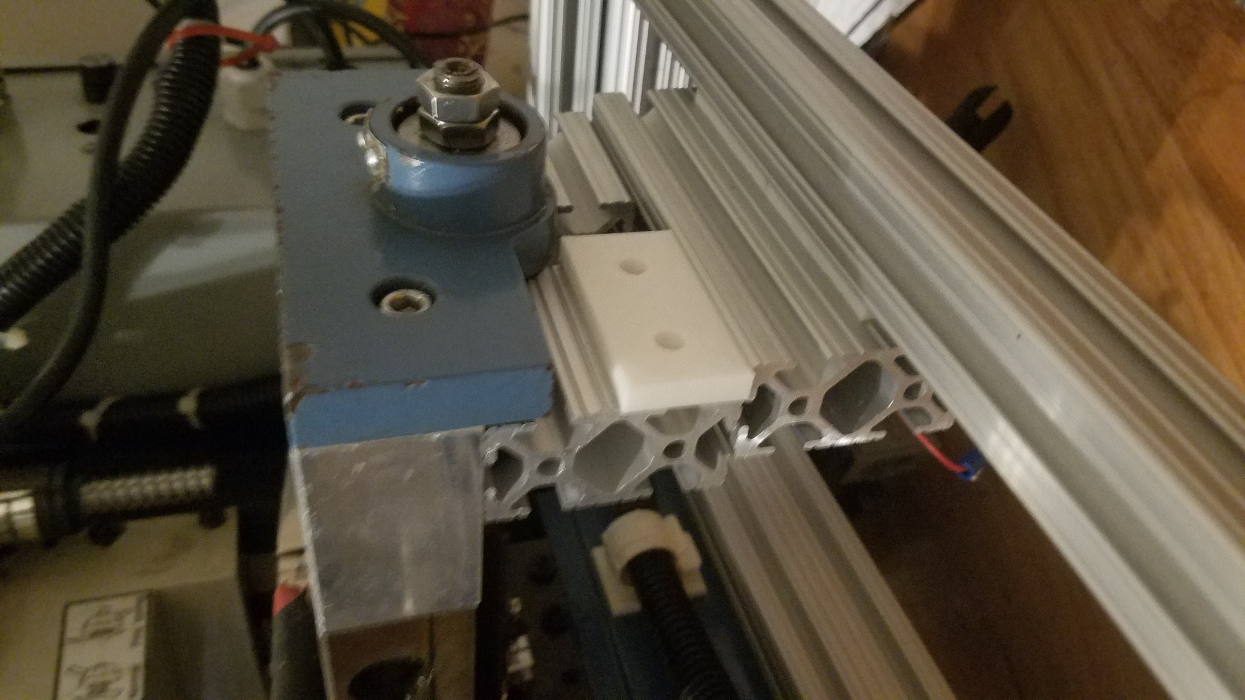
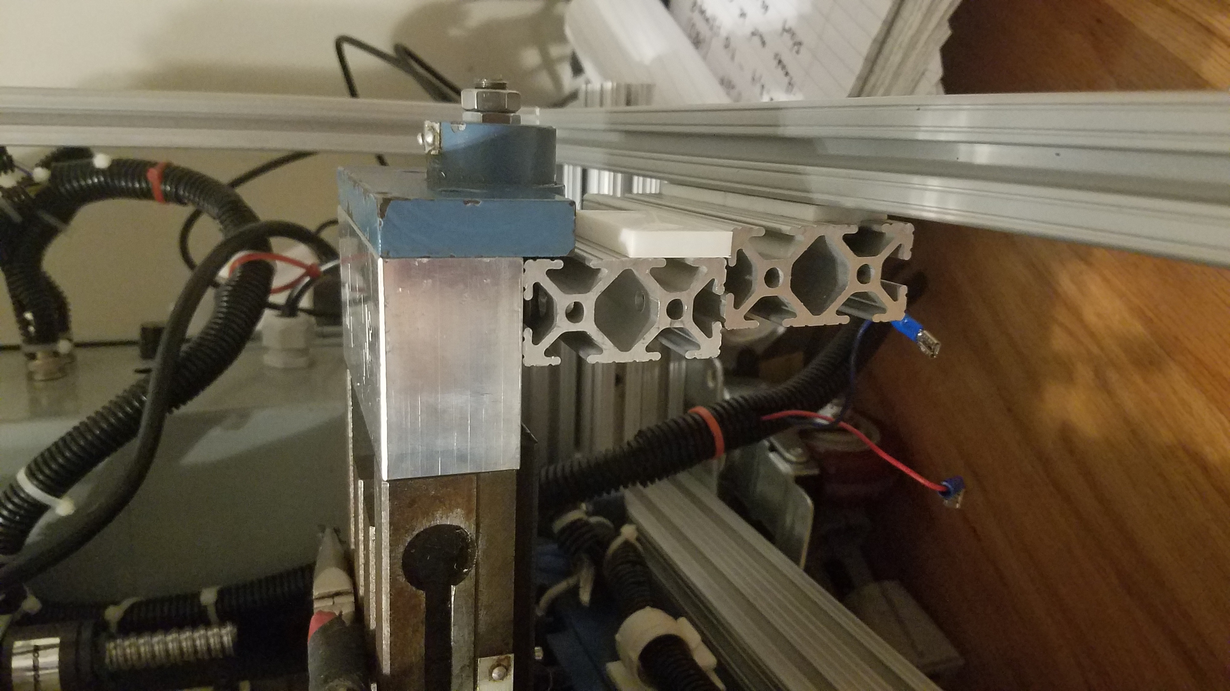
Connecting the motor side of the x/Y table to the Top Enclosure. The white 3d Printed spacer is required to make everything fit correctly.
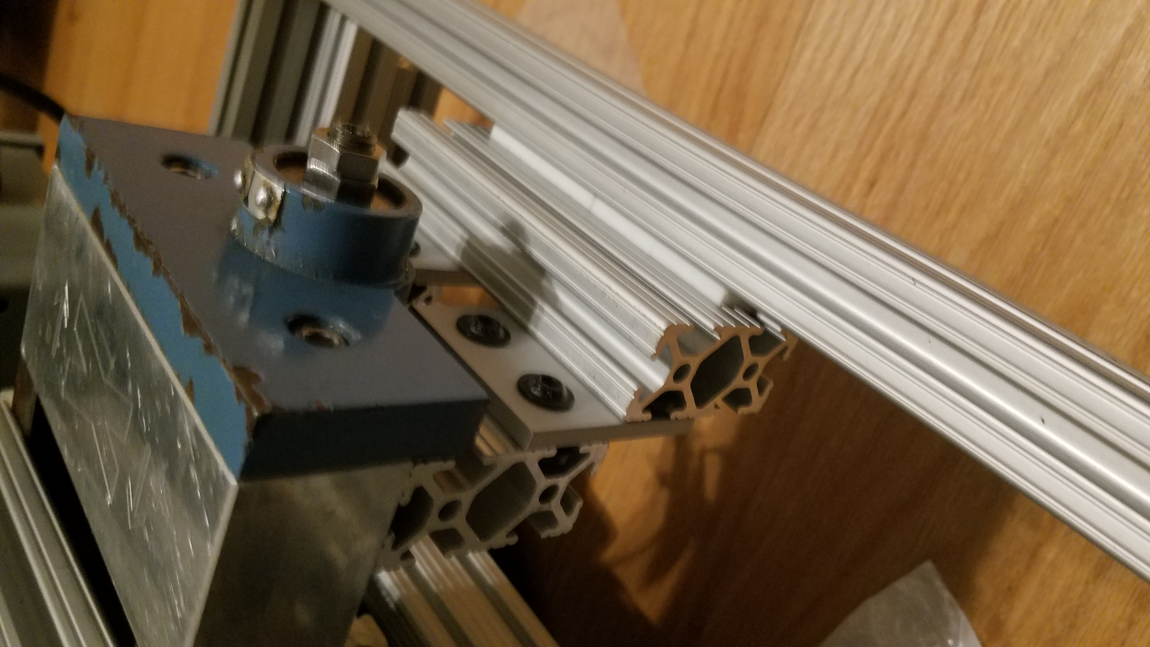
Another angle. Dry fitting before we physically connect the slide to the X/Y table.
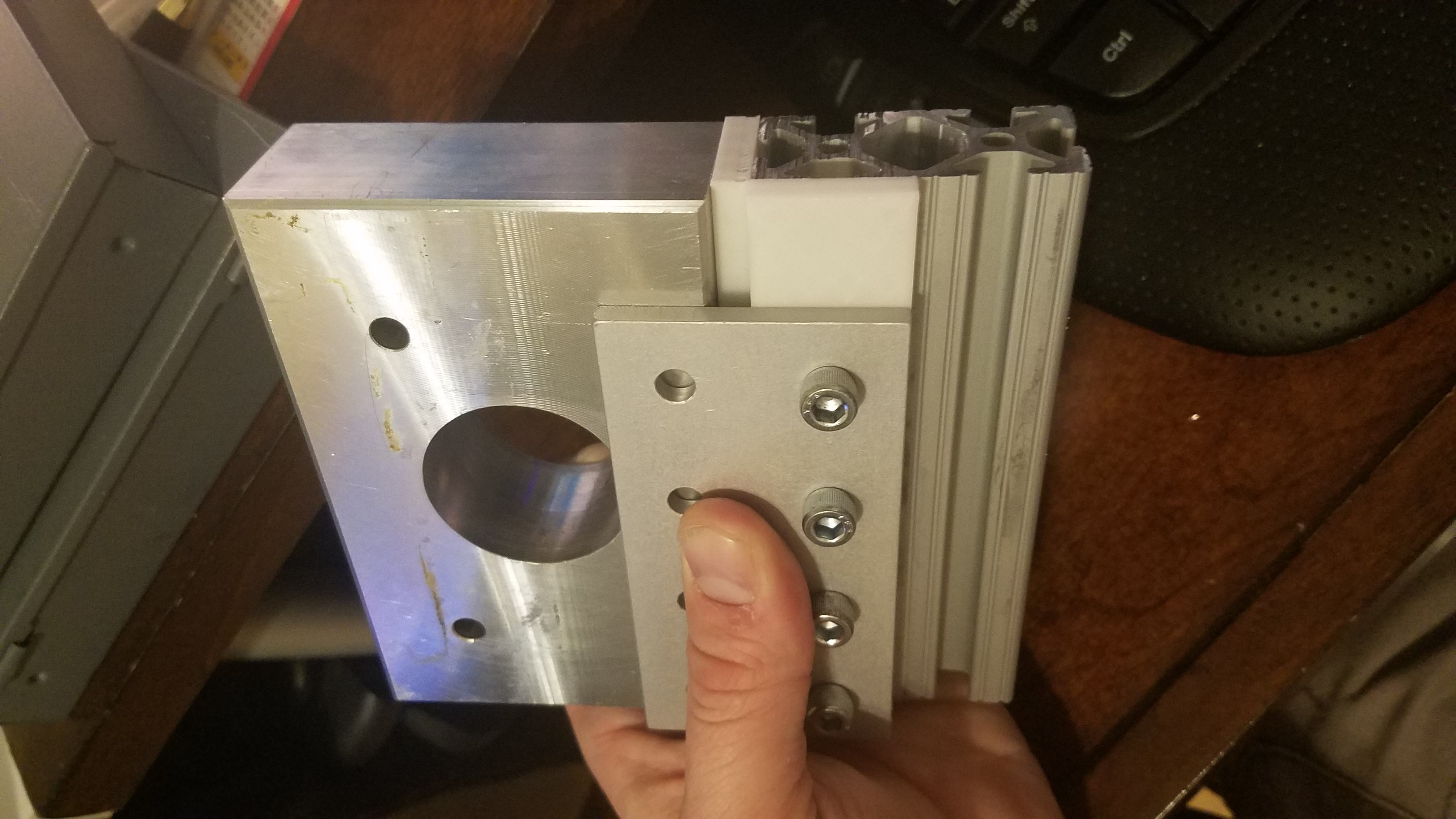
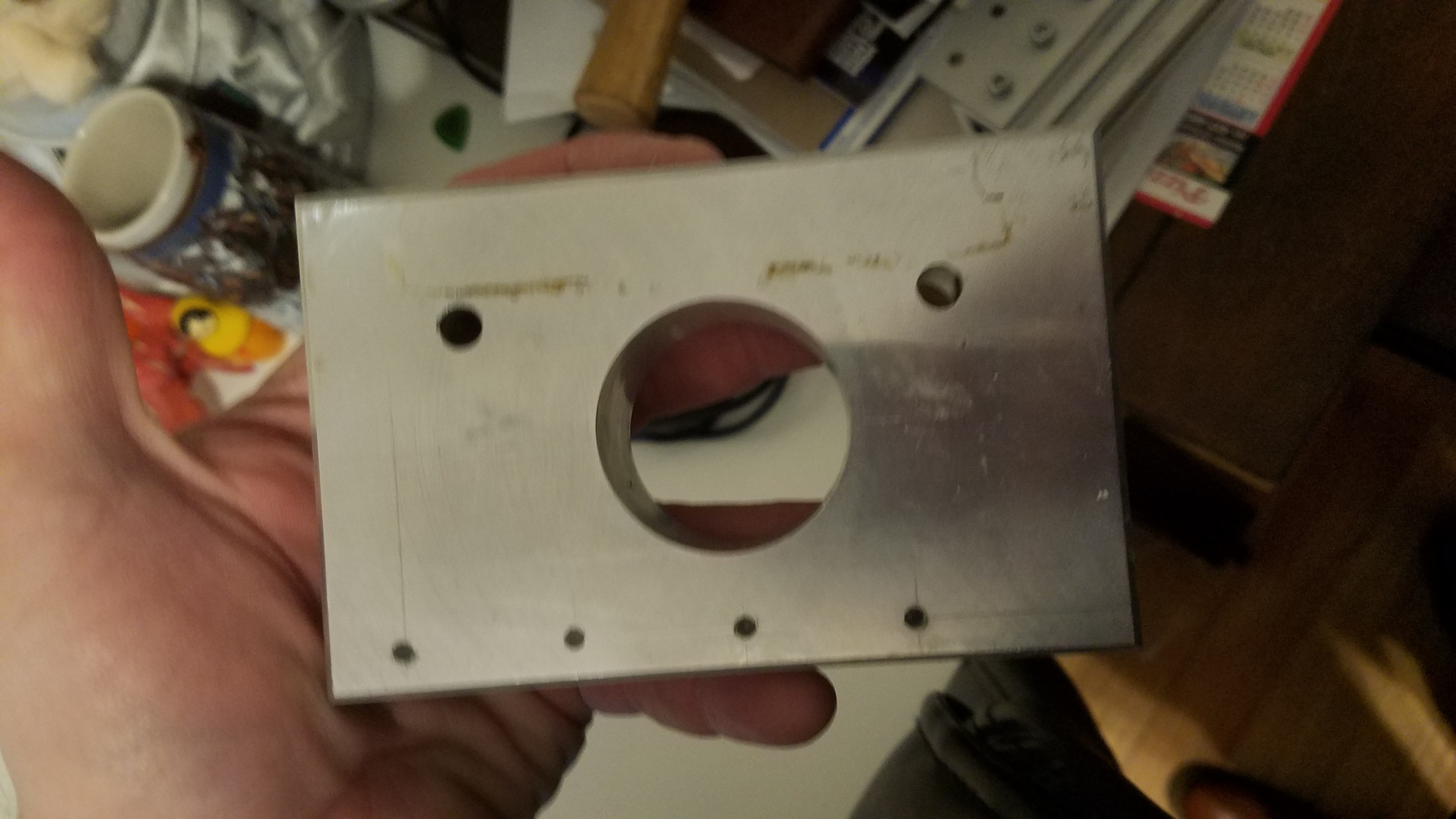
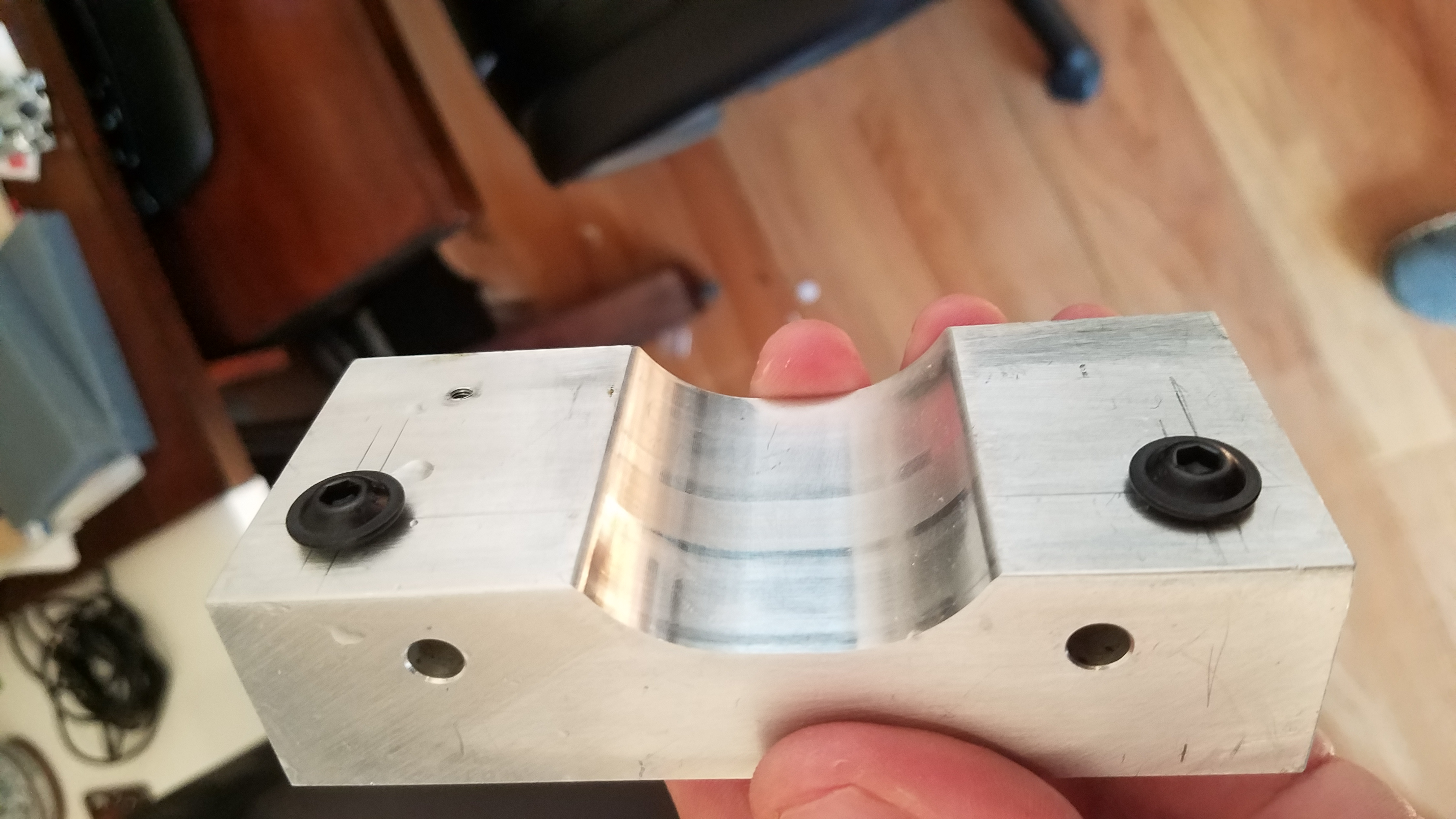
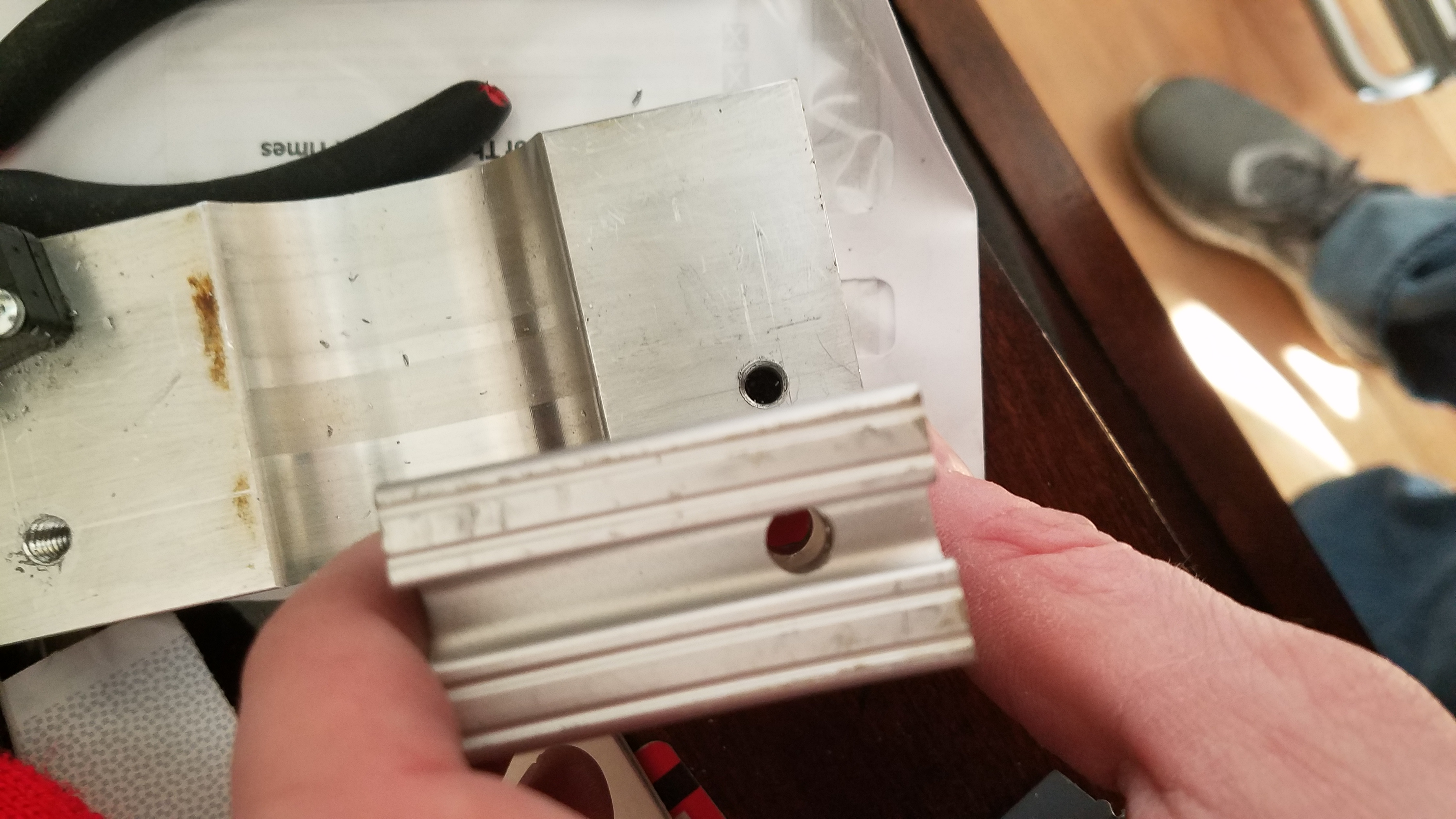
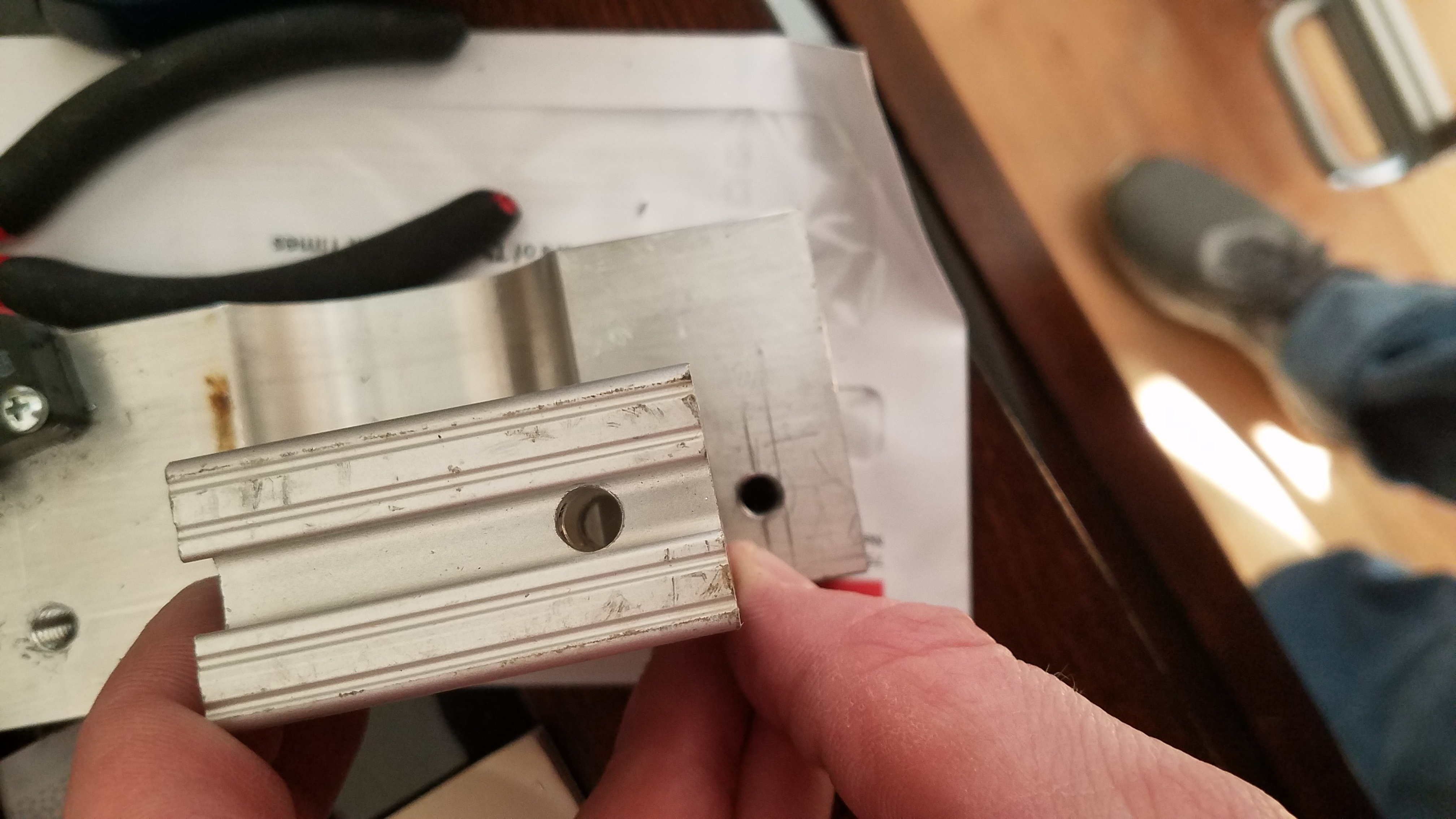
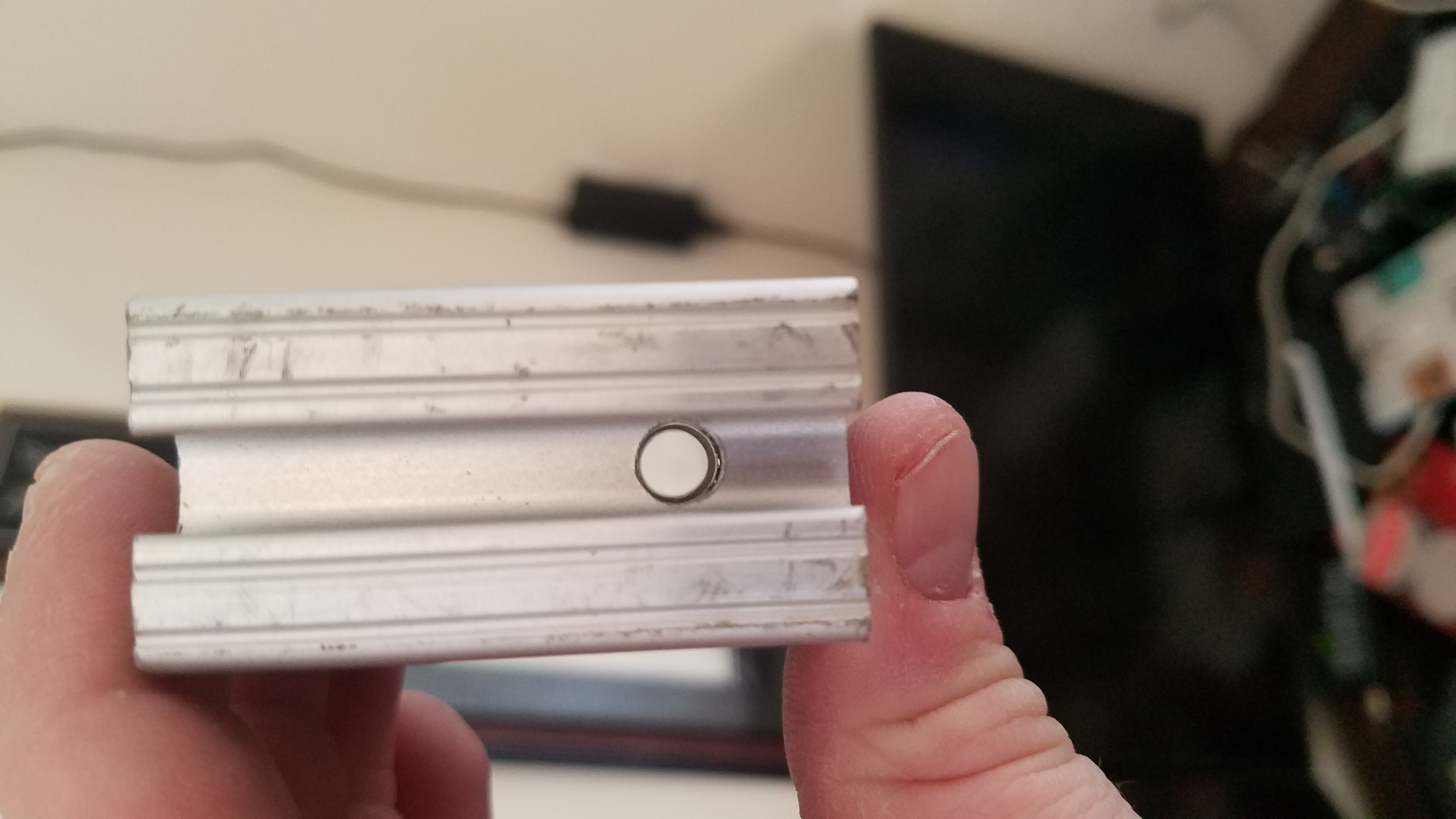
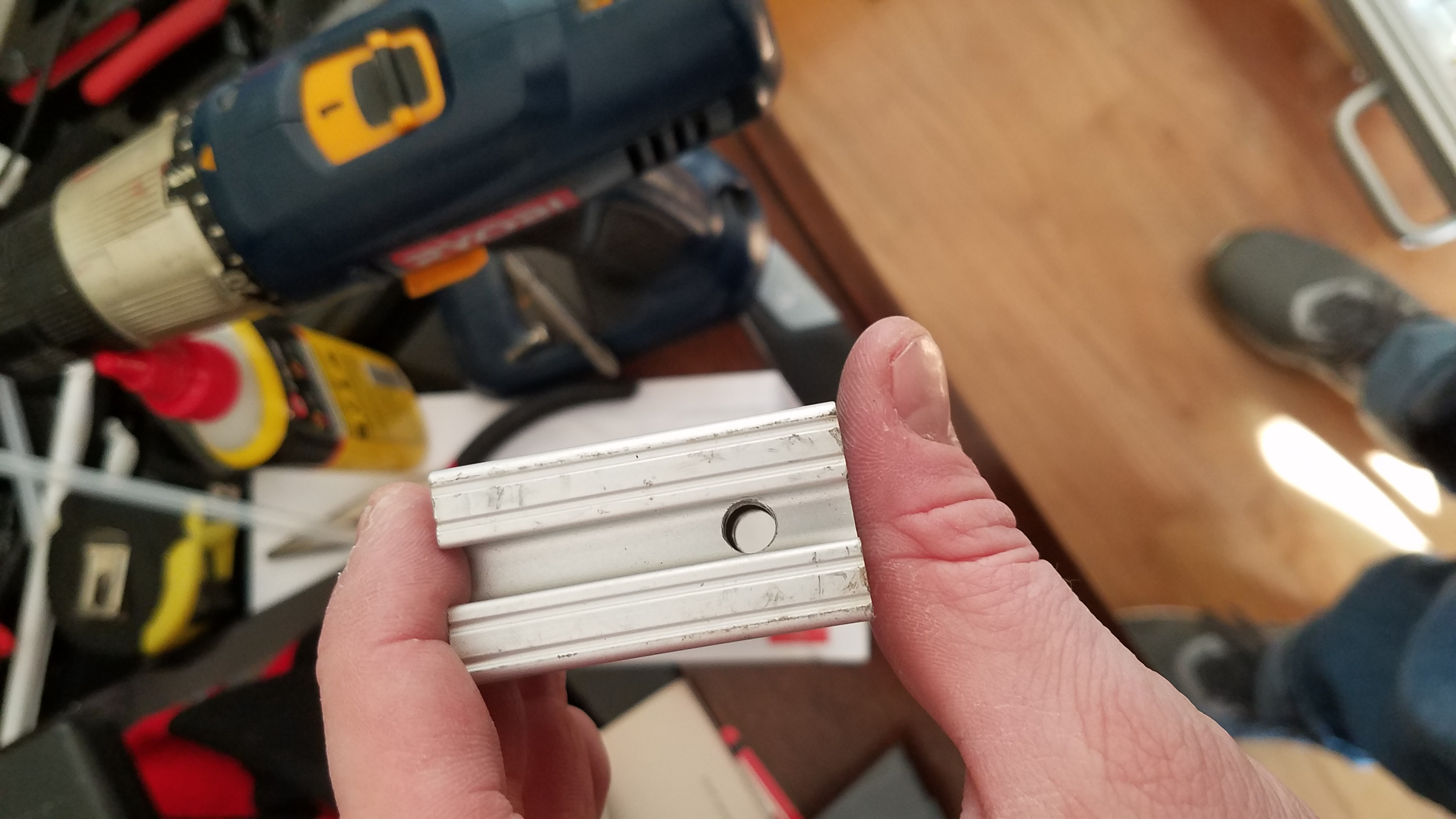
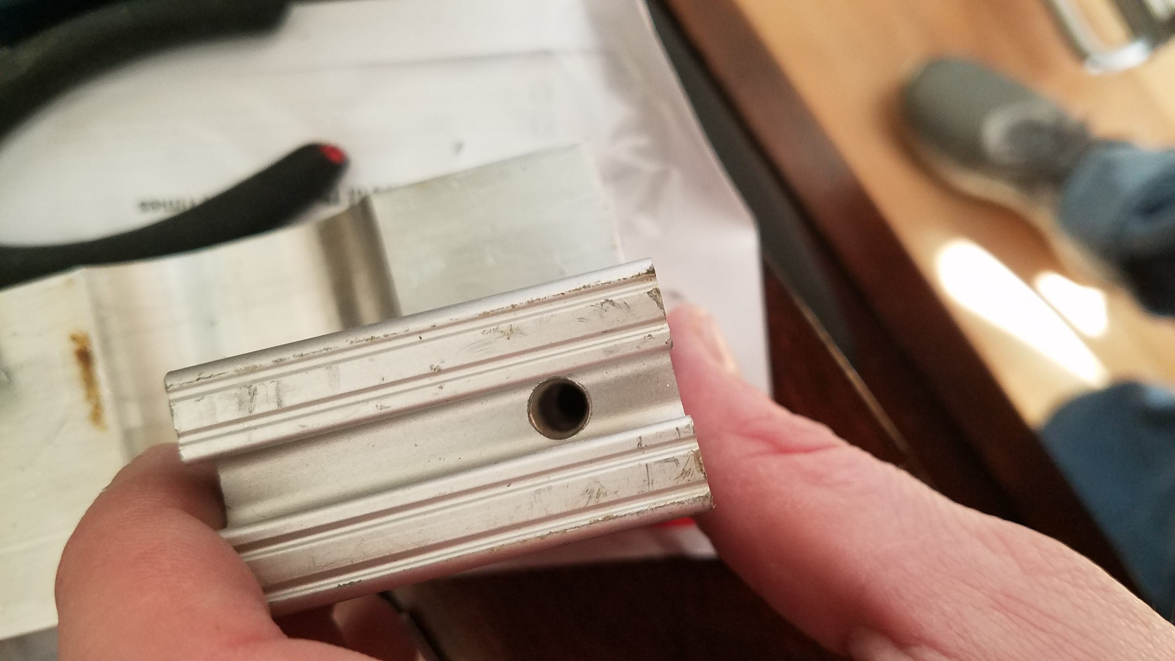
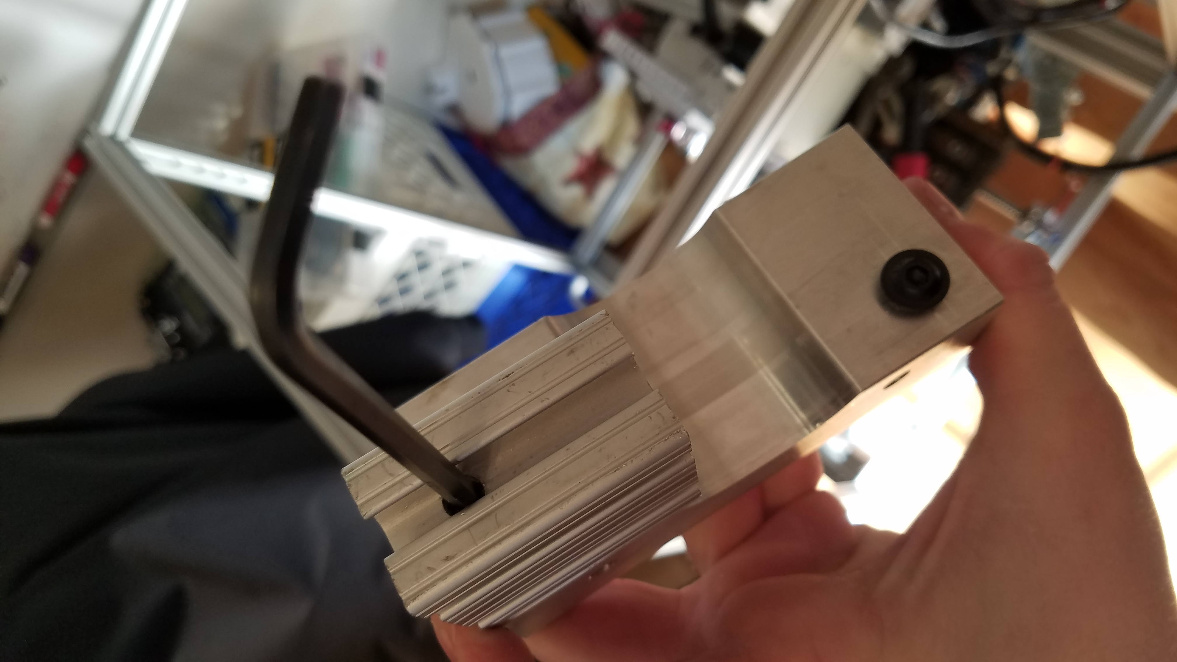
The AL block is the end of the X/Y table. The large hole is where the motor for the y axis passes. The motor mounts to the other side. The bracket faces the inside towards the CNC machine when mounted.
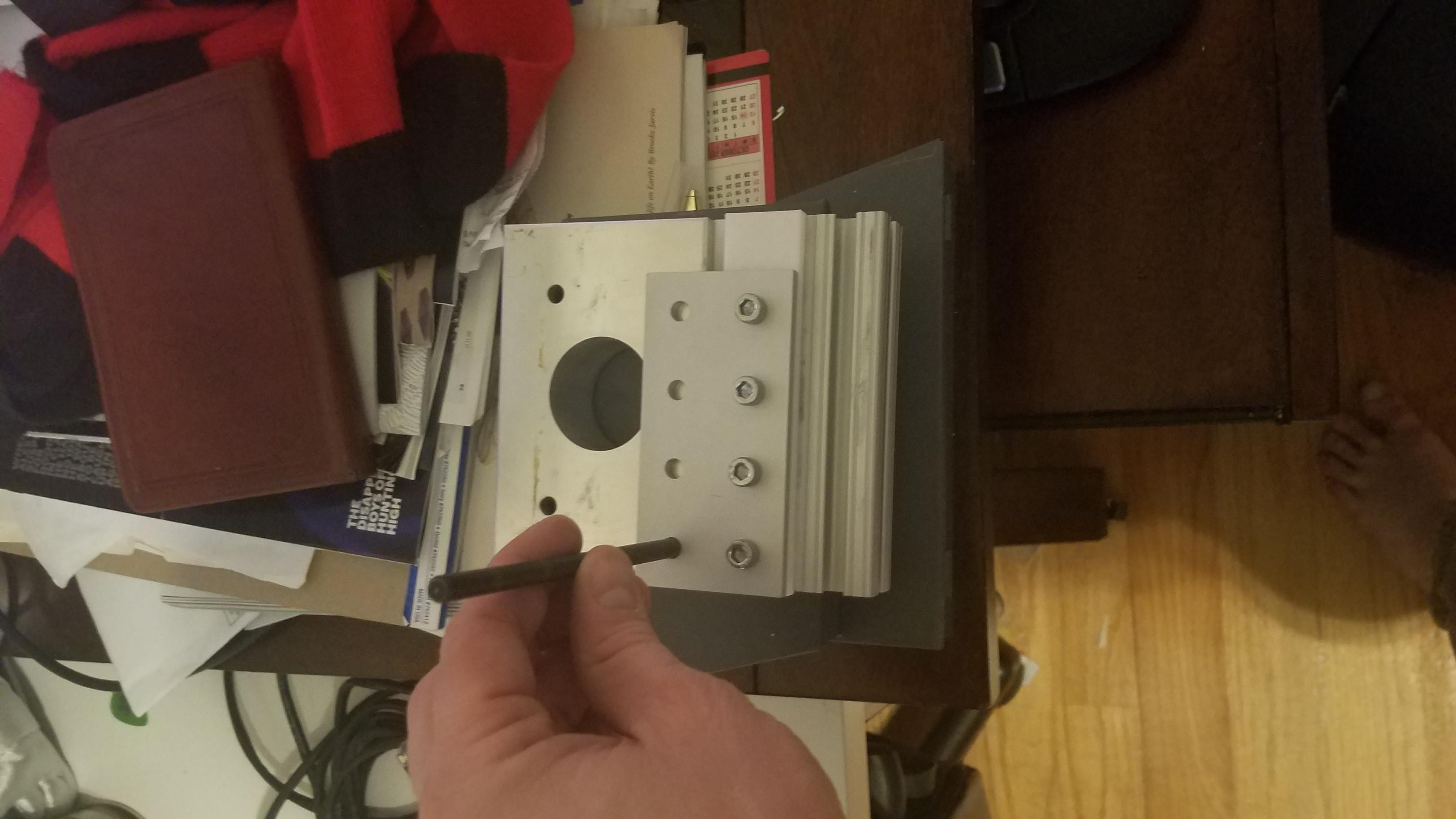
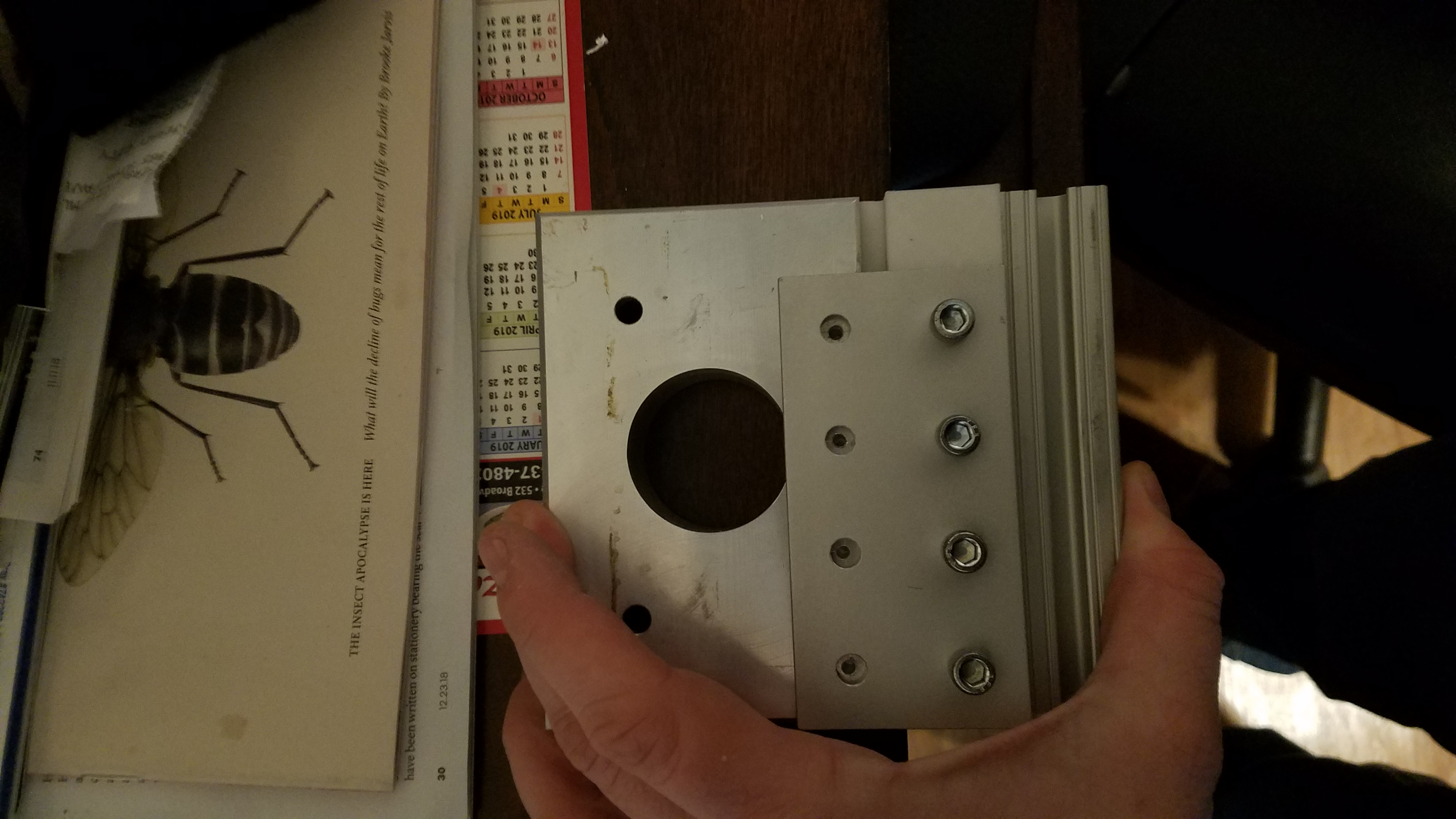
We are aligning the slide connection to the AL motor block and marking the bolt positions with a punch.
I used a center drill to start the mounting holes.
Picture to show alignment of the holes to the connection bracket.
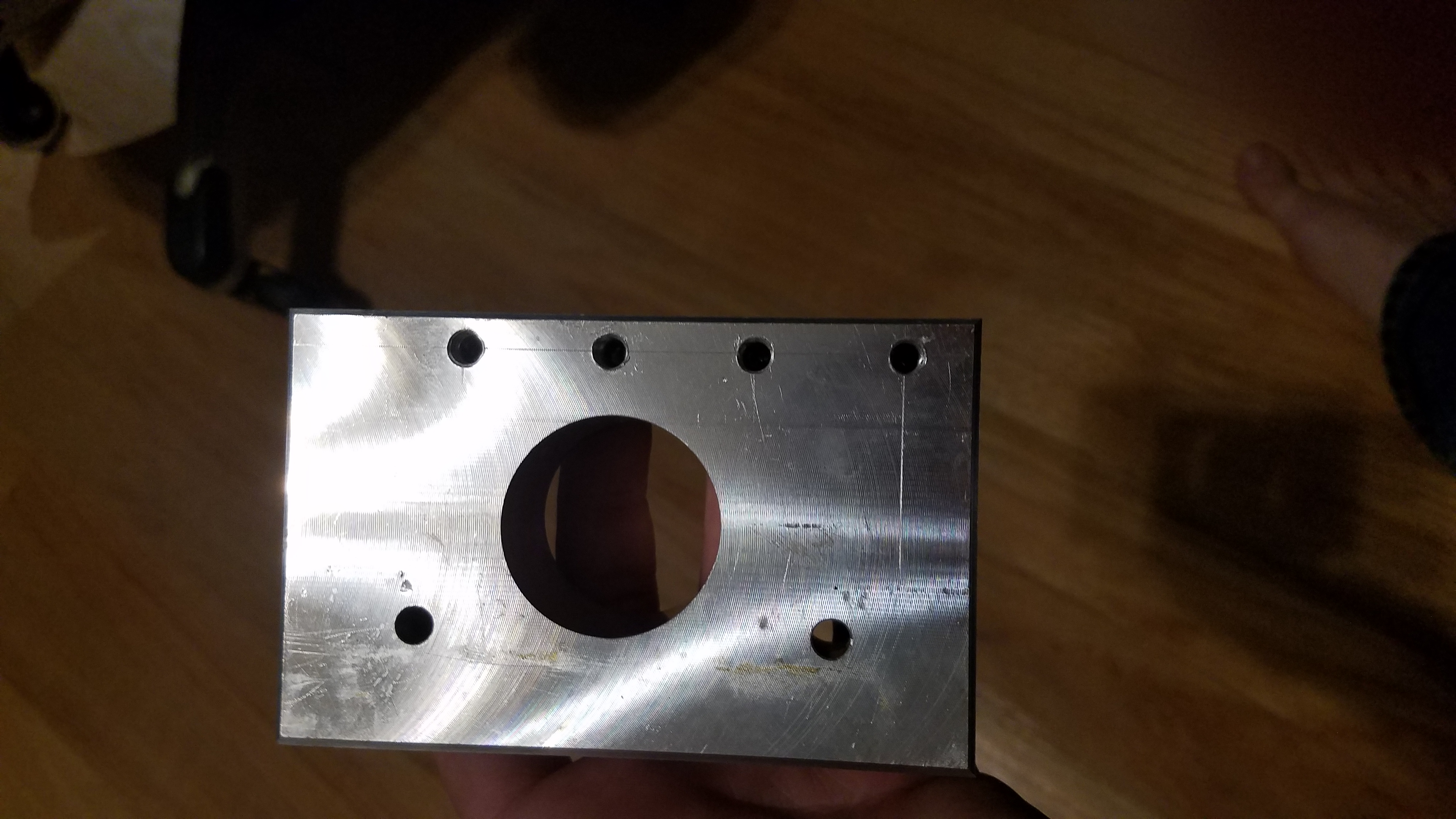
Drilled out the mounting holes with a #7 drill bit. We will be tapping these with a 1/4-20 tap.
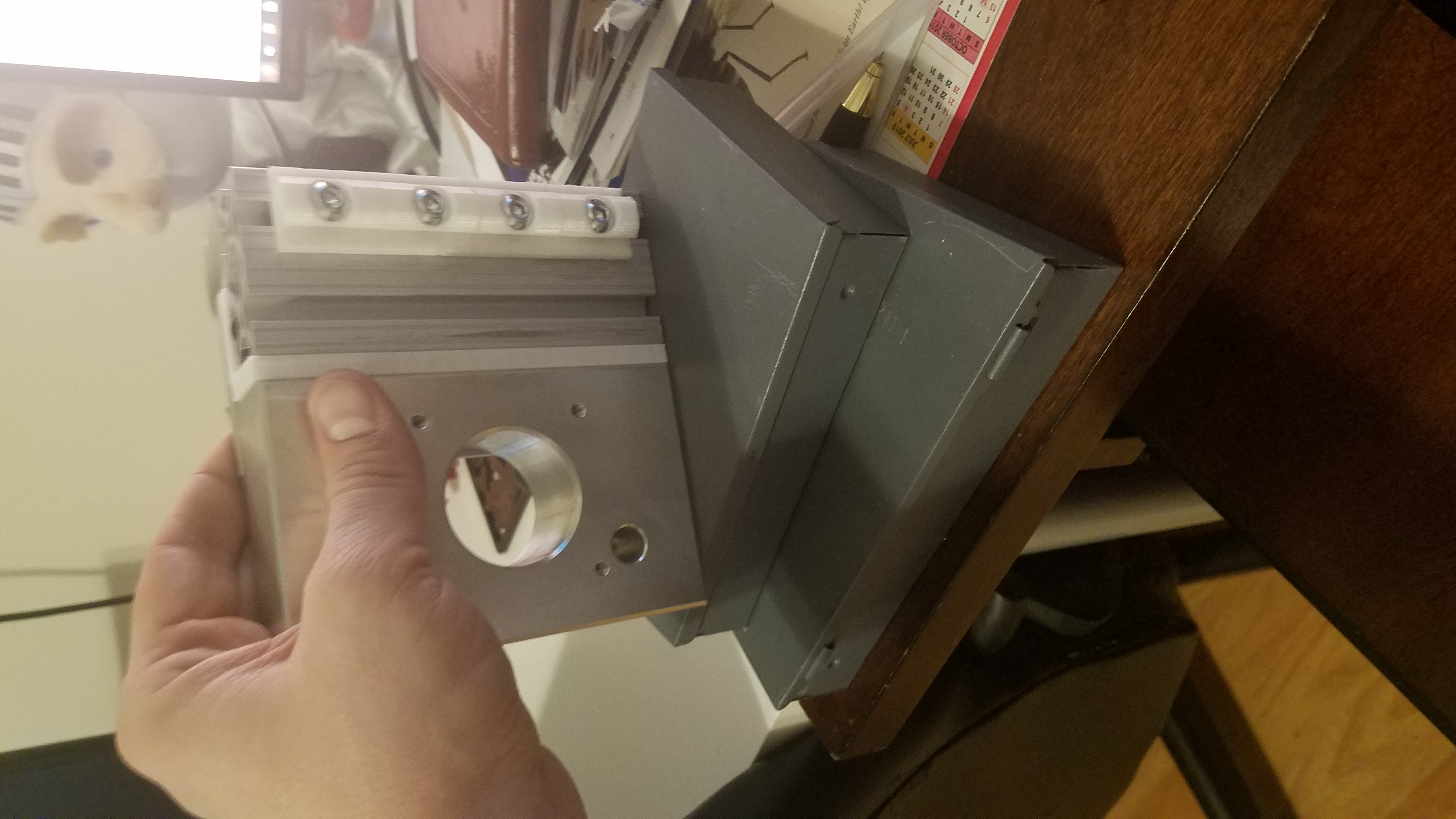
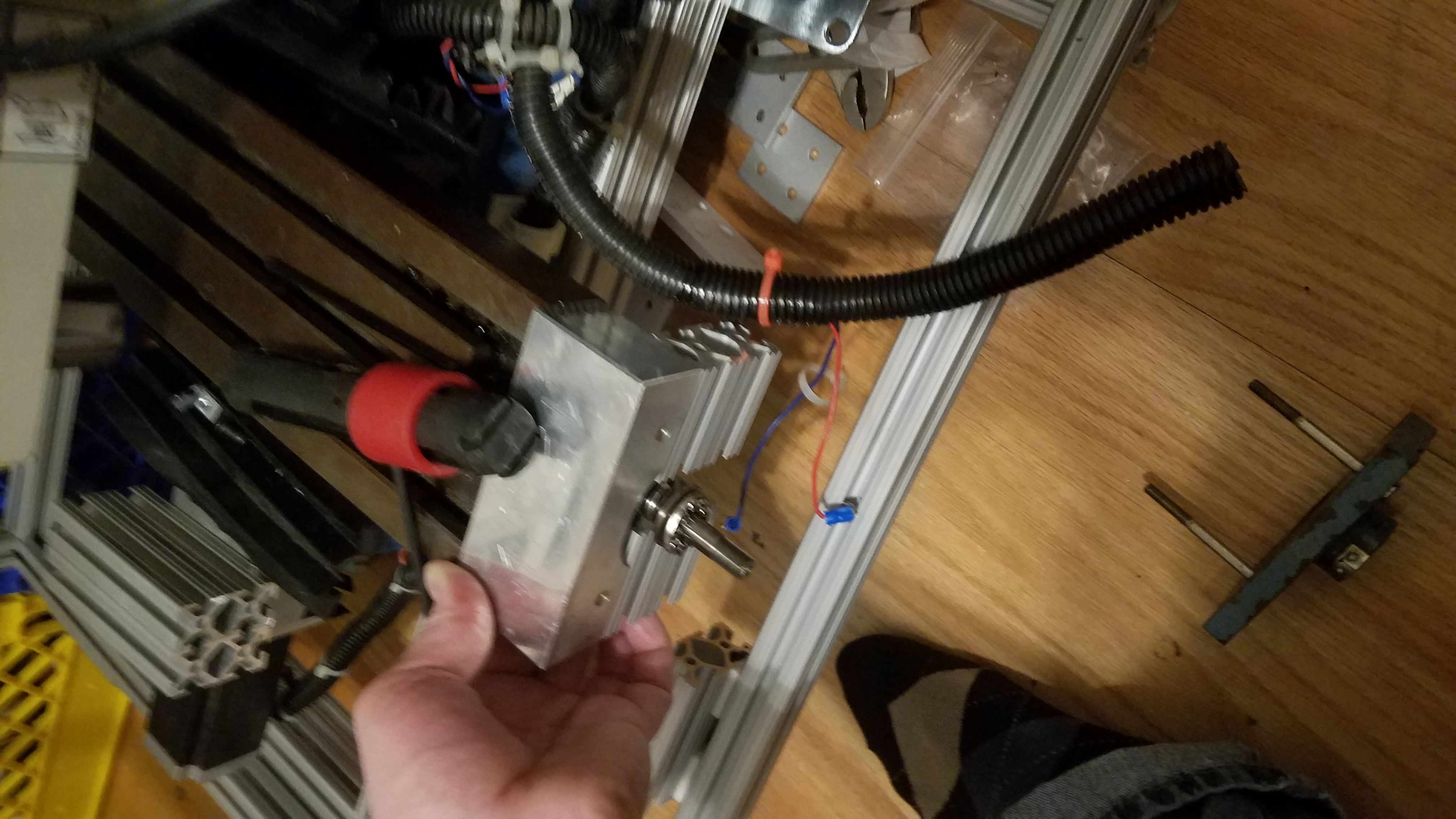
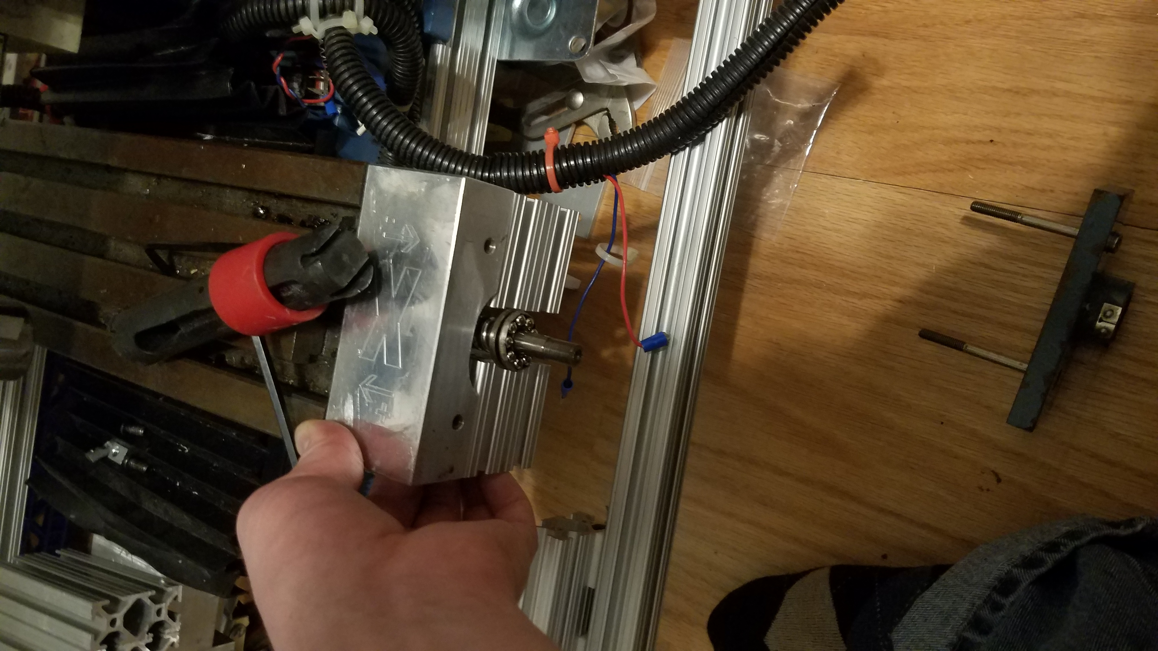
The block is joined to the frame with a 80-20 linear bearing(white) this allows the component to move along the rail in the direction of y axis movement. The AL bracket is obsured by the AL motor mount block.
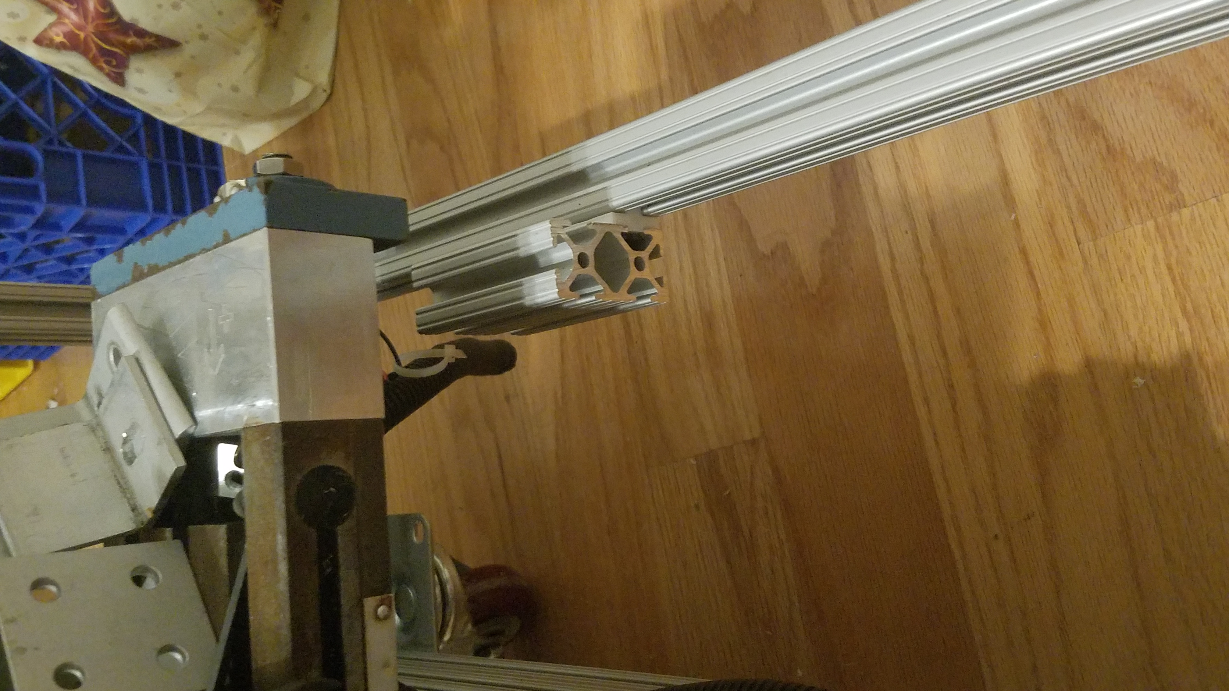
Linear bearing shown in rail that forms the bottom of the top enclosure.
Rail mounted in enclosure and the AL mounter mount block reattached to the CNC X/Y table.
Non motor side
I tapped 2 holes into the non motor side end of the X/Y table. This will allow us to attach a tslot section. Each hole is 1/2 in from the edge in both X and Y.
AL bracket with Tslot nuts. Side view
AL bracket with Tslot nuts. Bottom view.
Marking access hole. 1/2 in from the end. This will allow us to tighten the screws above.
1/4 in access hole drilled.
Attaching the spacers to the X/Y non motor end.
Both sides mounted.
Reattaching the X/Y non motor end to the X/Y table.
A side view of a linear guide and spacer assembly.
Linear 80-20 slide in frame.
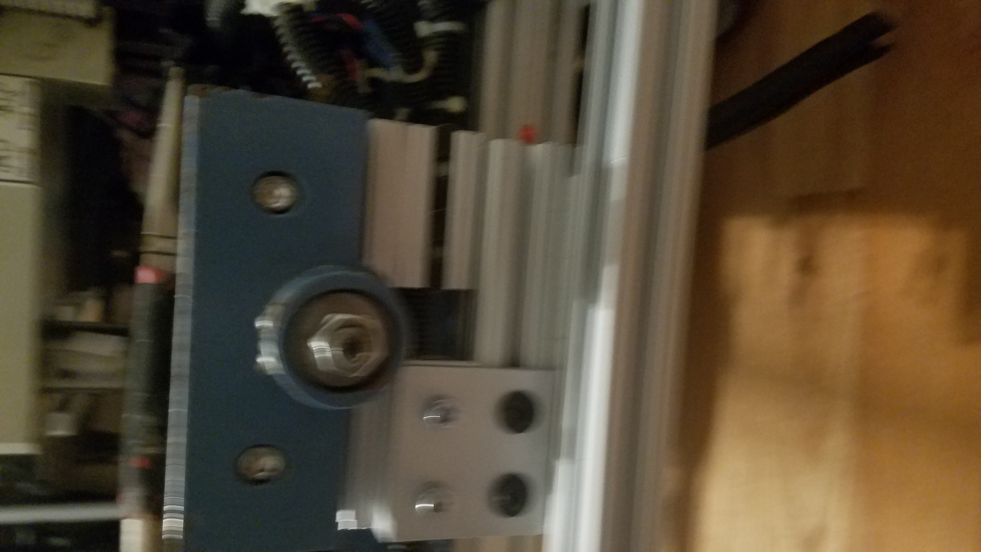
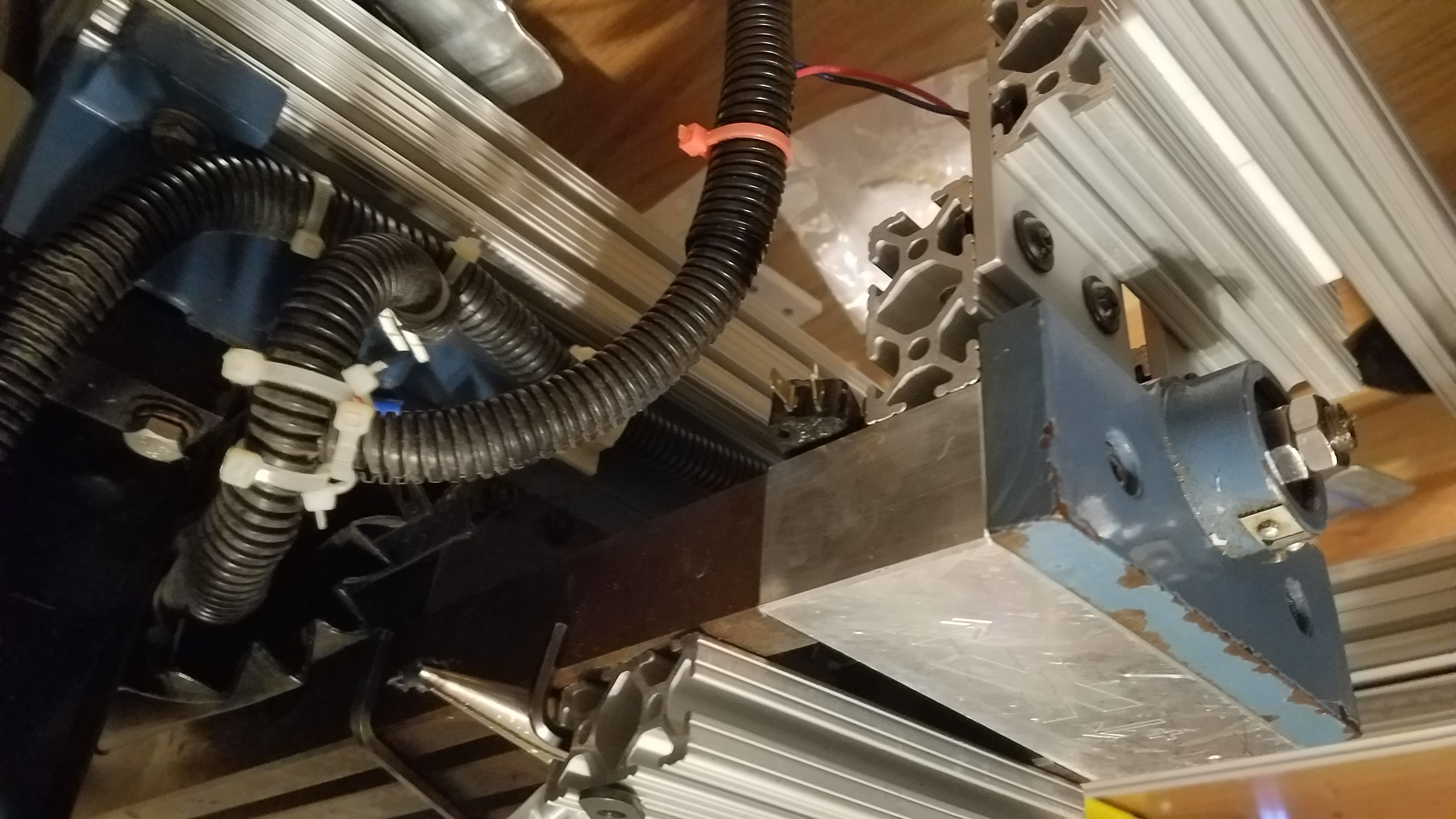
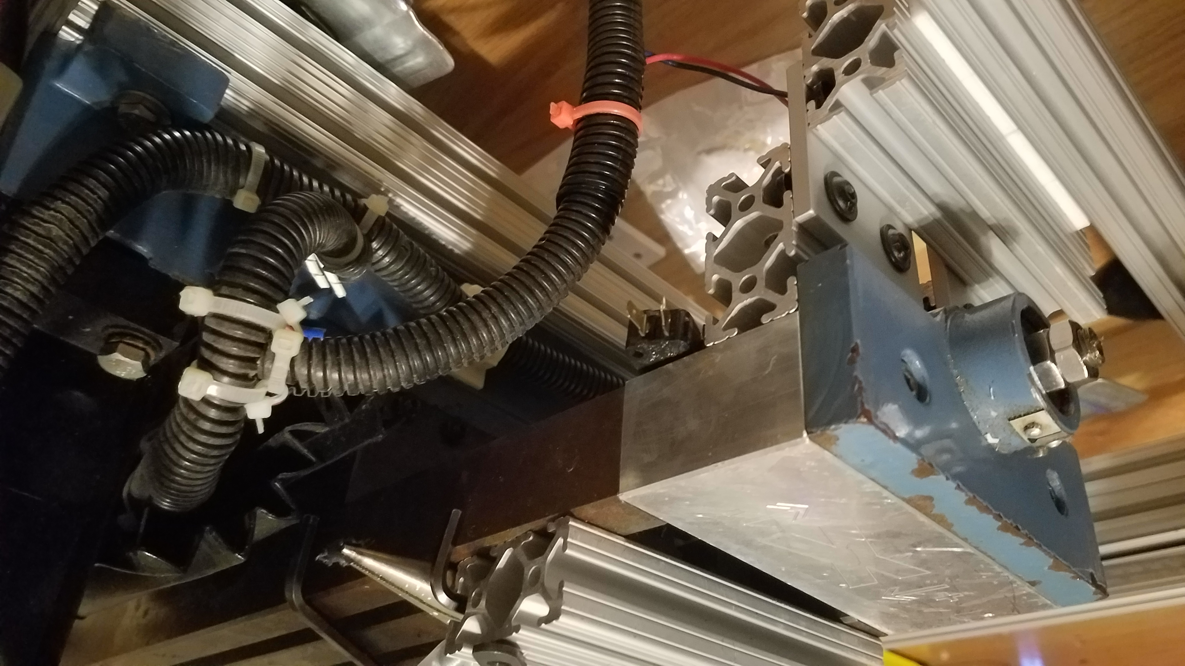
Connecting the X/Y table non motor side to the bottom of the Top Enclosure Frame.
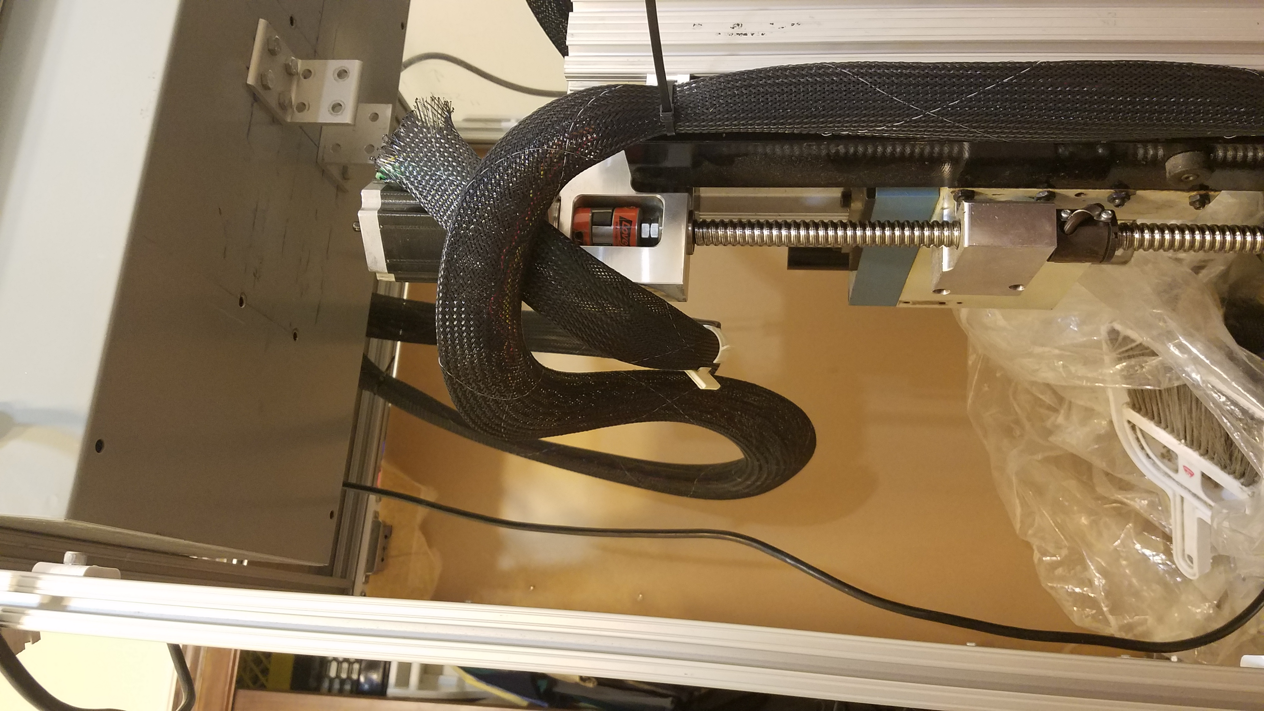
View of linear bearing on the non motor side. The linear bearing slides inside the rail.
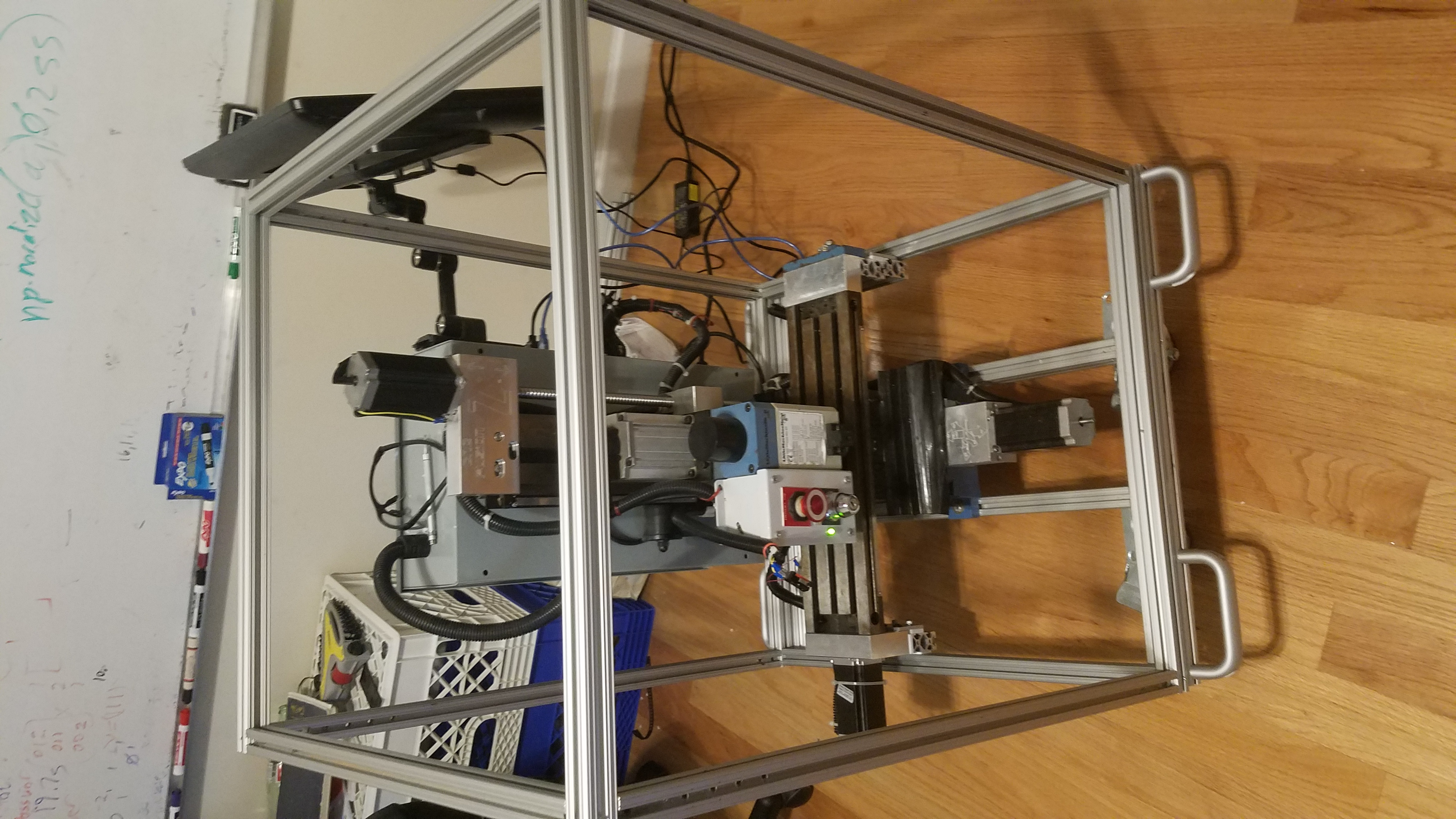
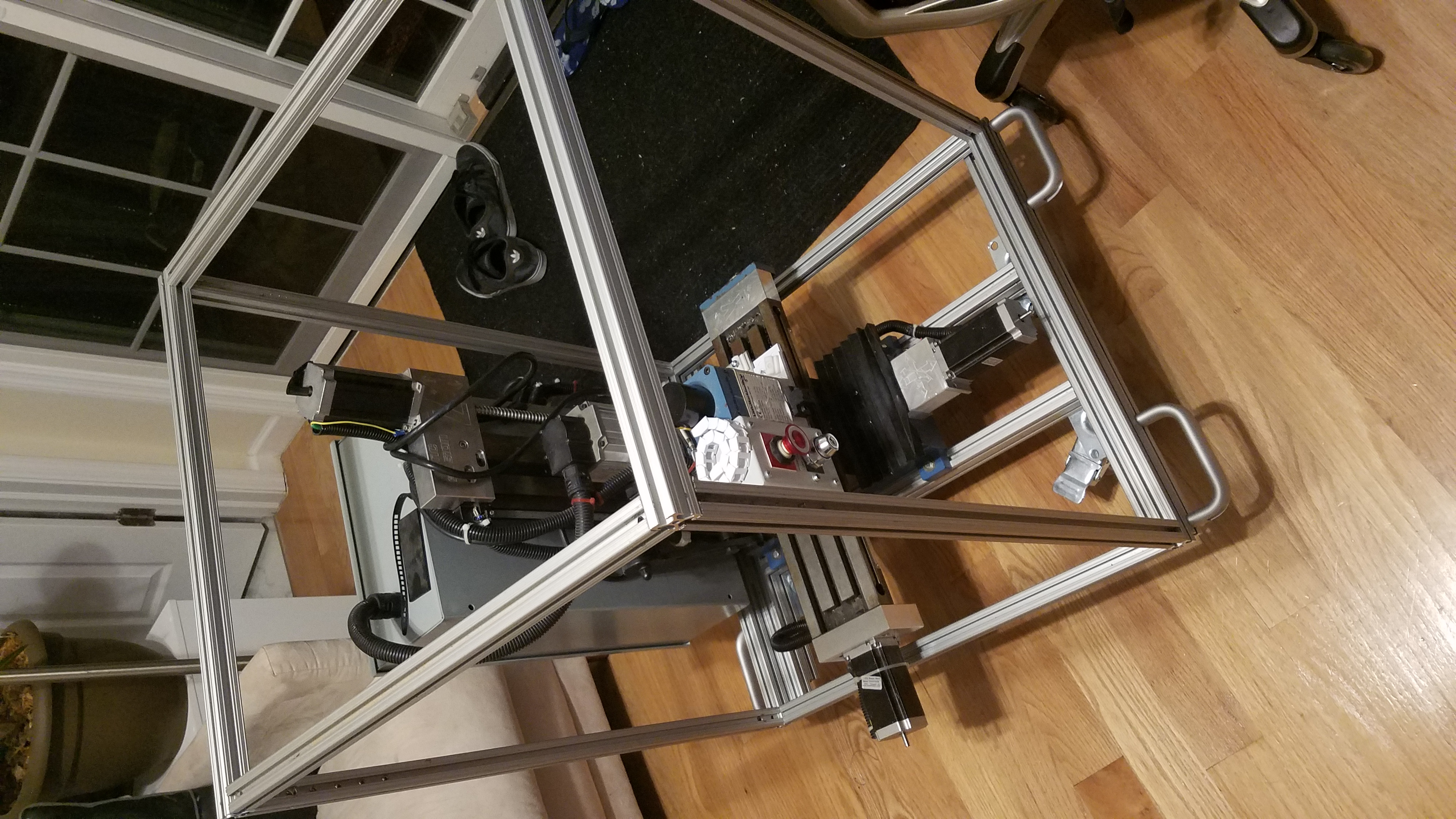
Both Sides of the X/Y table attached to the frame. The Y axis moves front to back within the frame while the x axis moves the top frame left to right.
CNC moving.
Wiring
Spindle Control
Rerunning the spindle control wiring
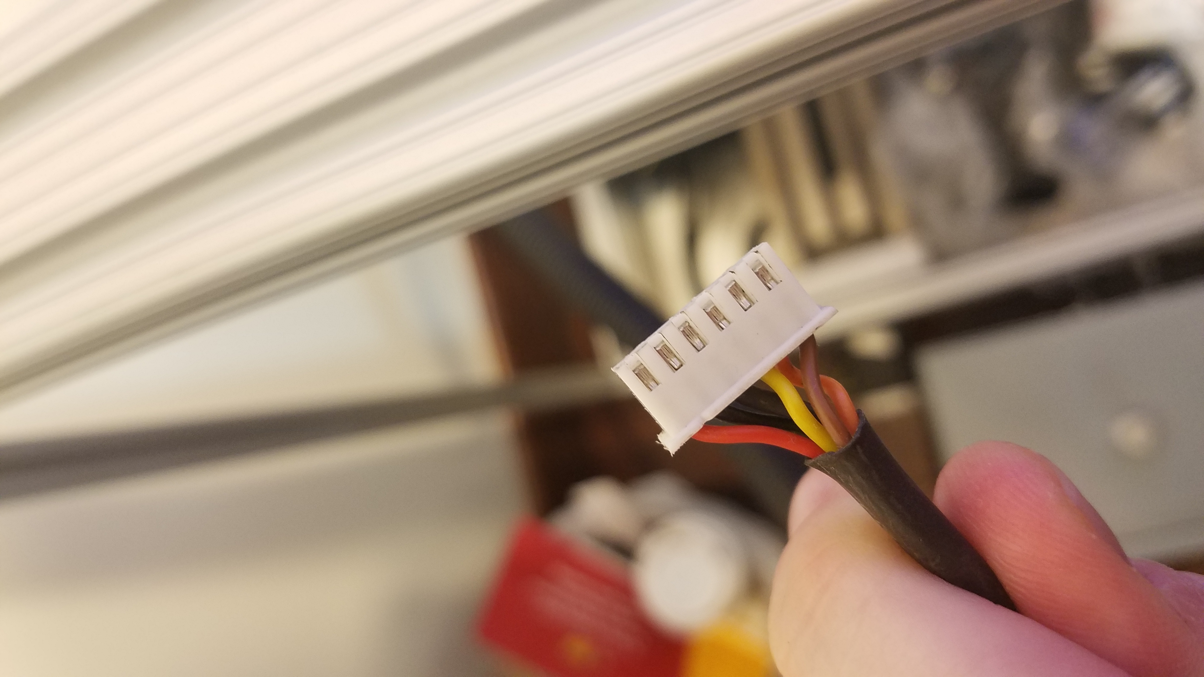
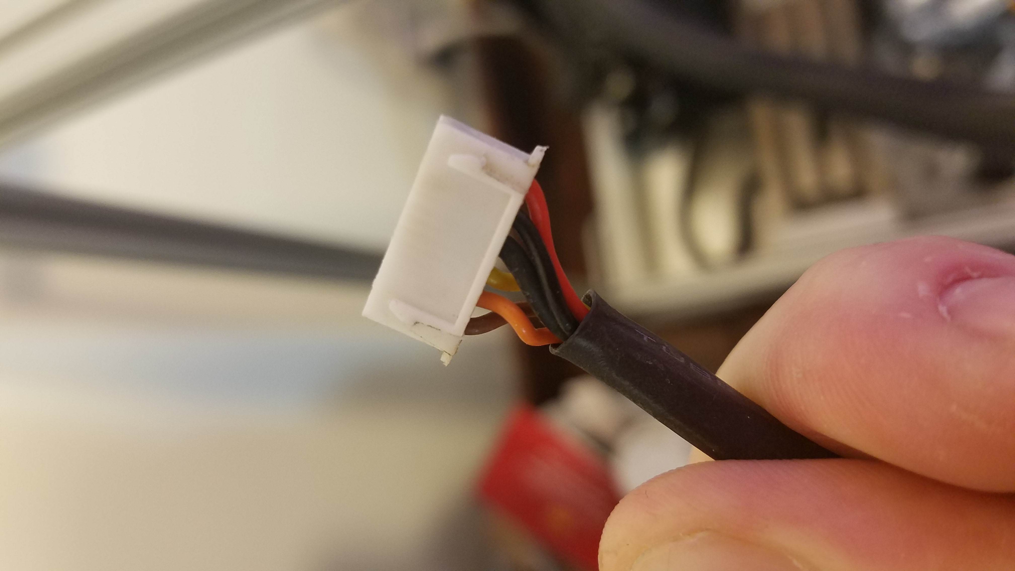
Wiring junction for the X/Y table endstops
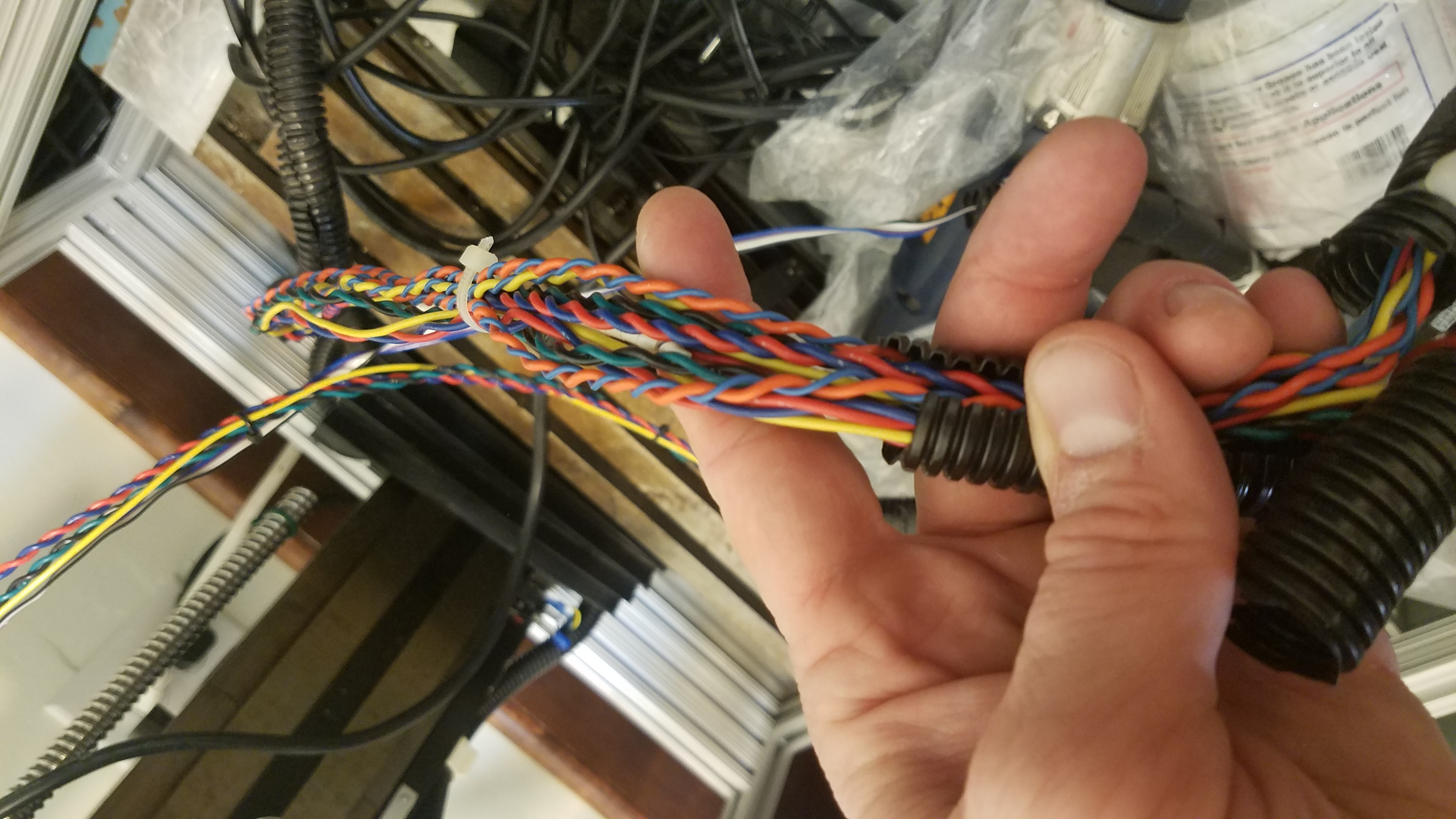
End stop wiring and stepper motor signals. All twisted pairs to reduce noise.
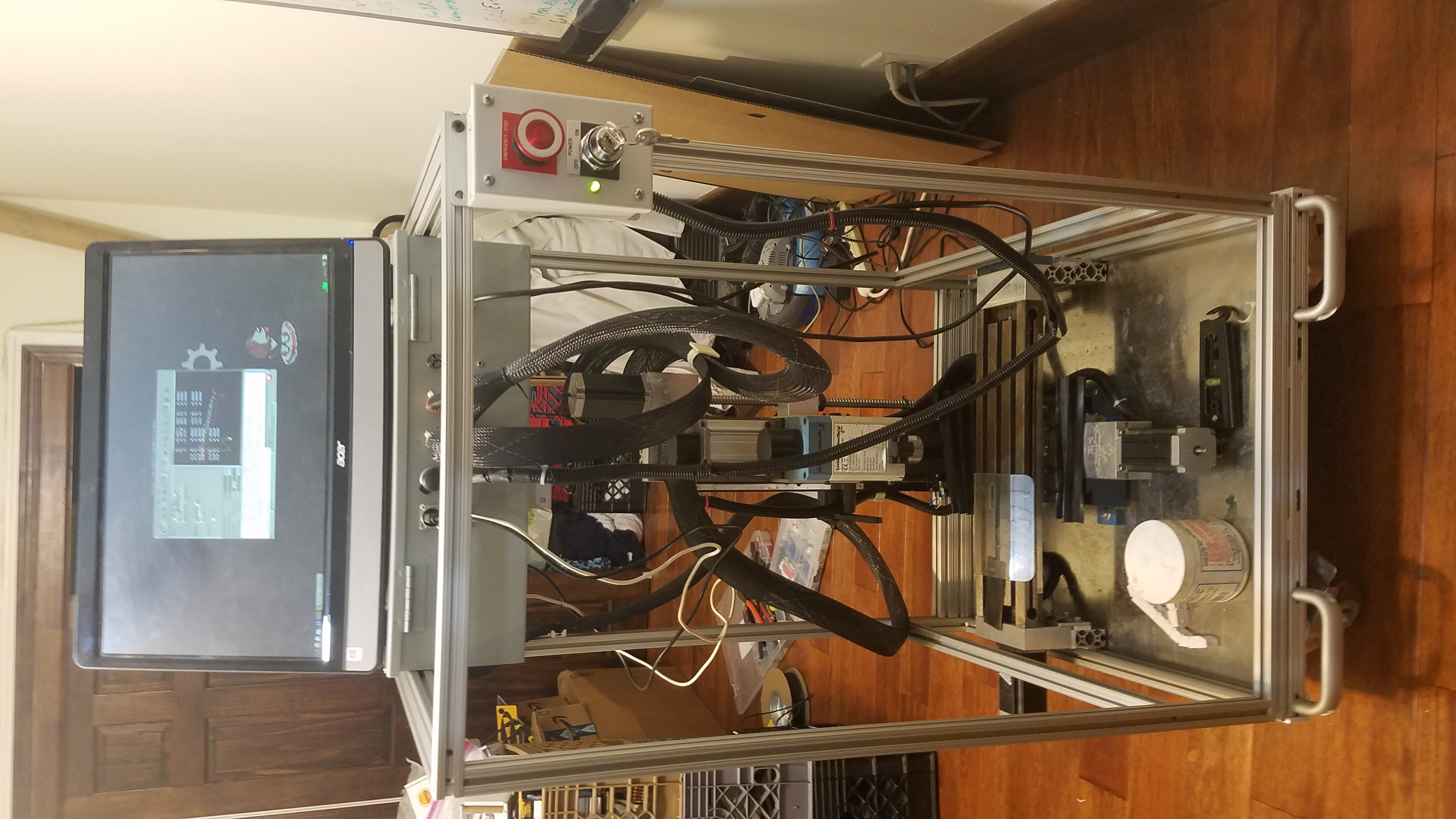
Testing with Linuxcnc.
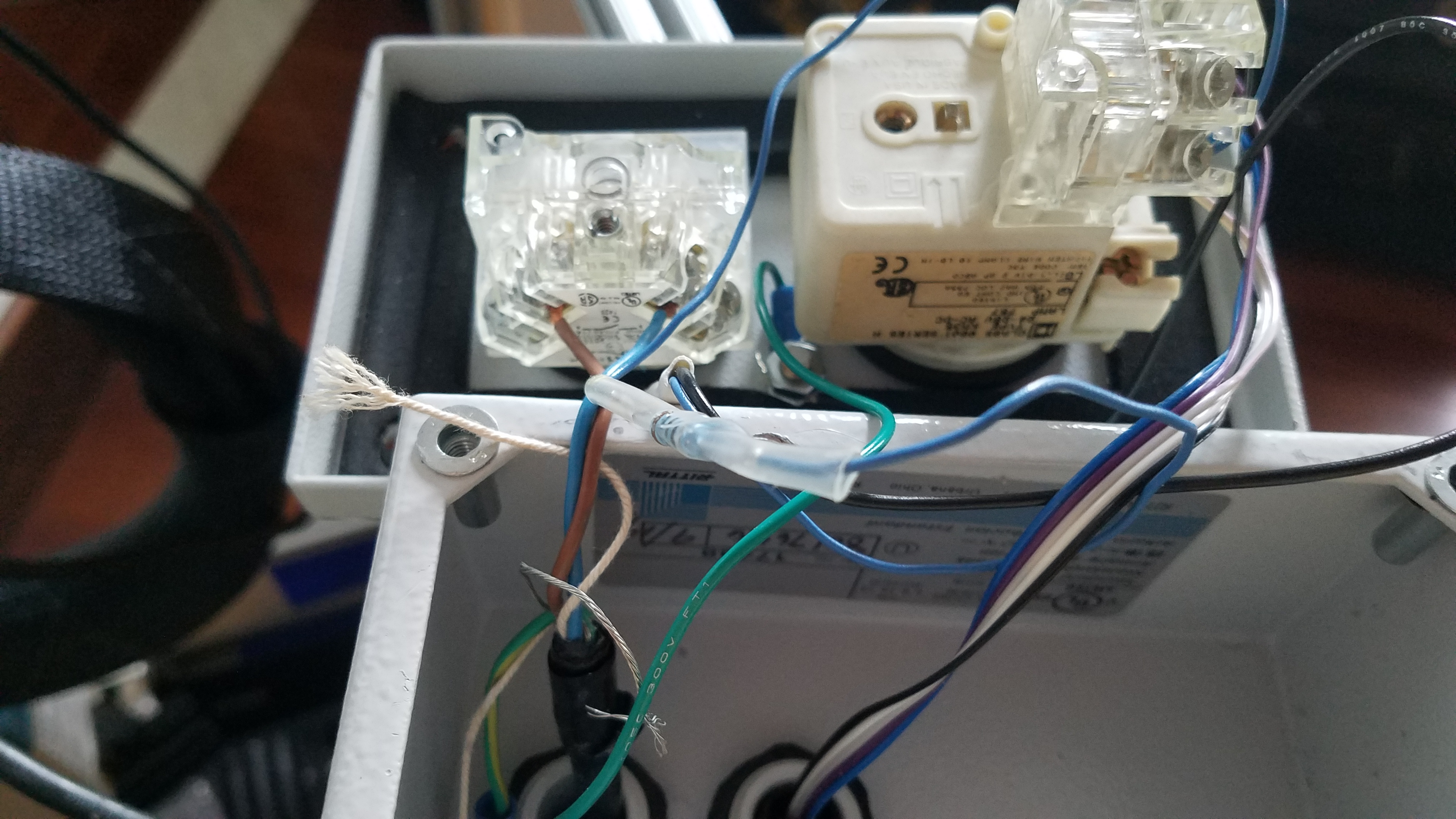
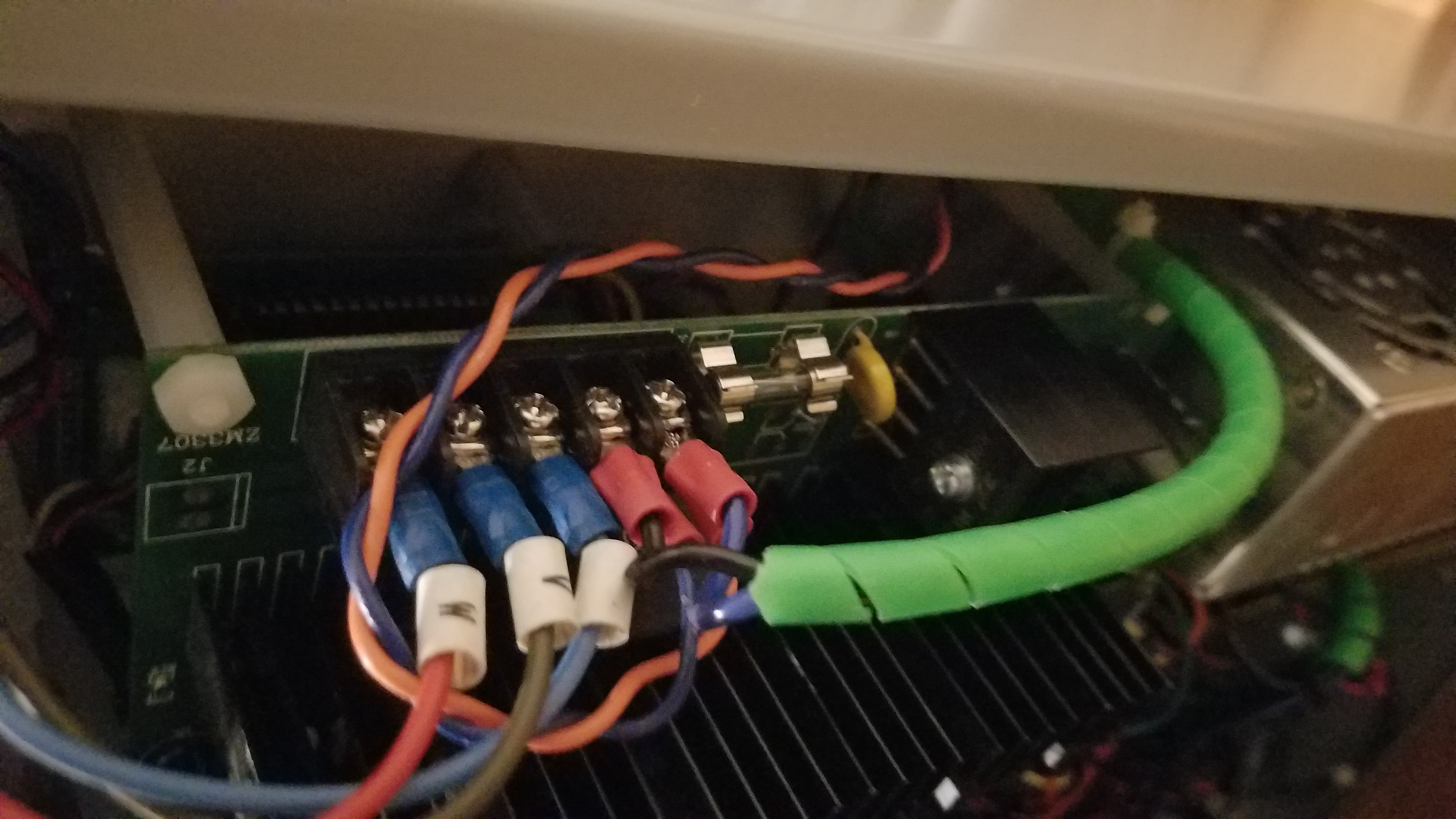
Inside power switch and Estop enclosure.
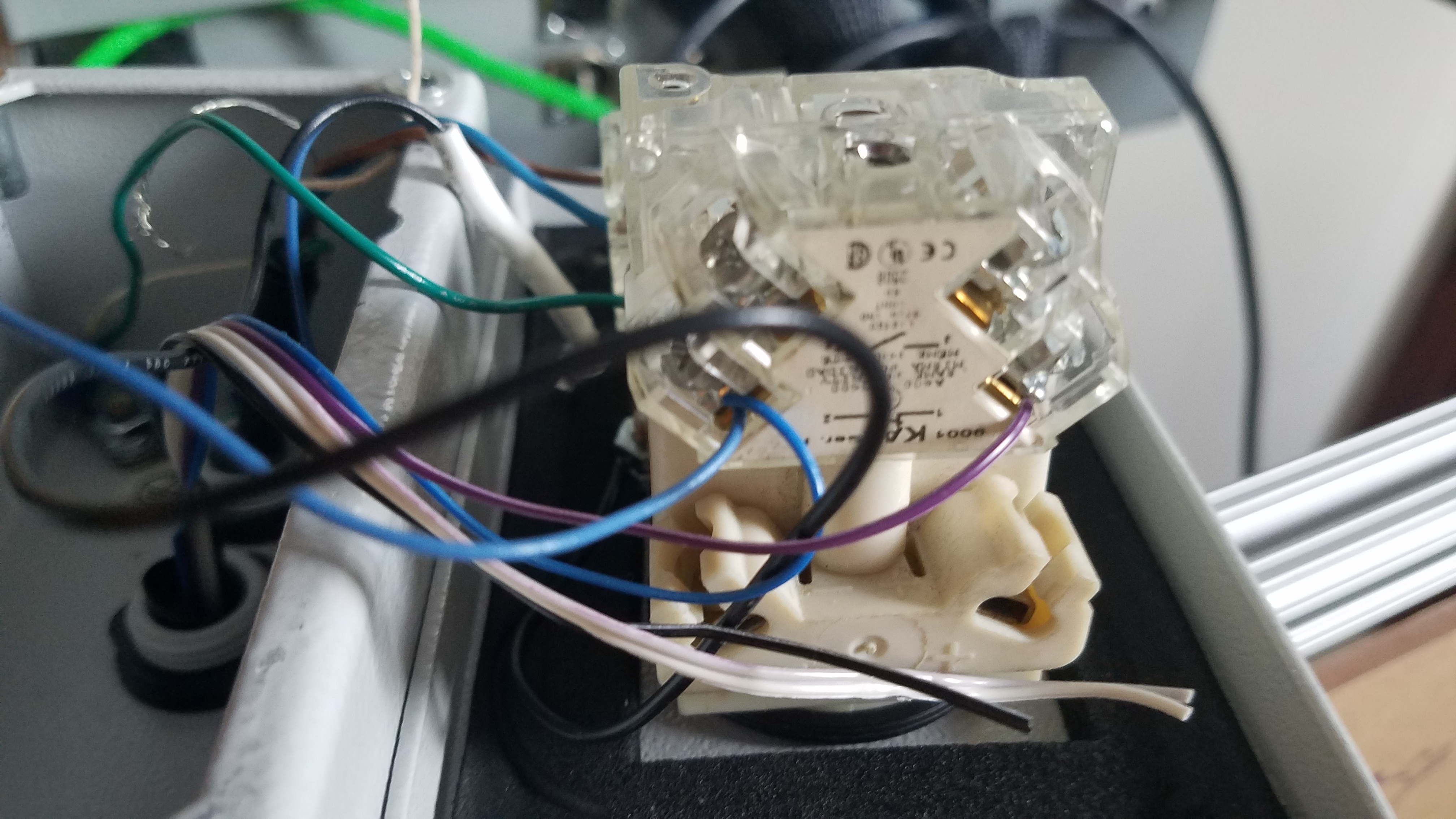
Inside power switch and Estop enclosure.
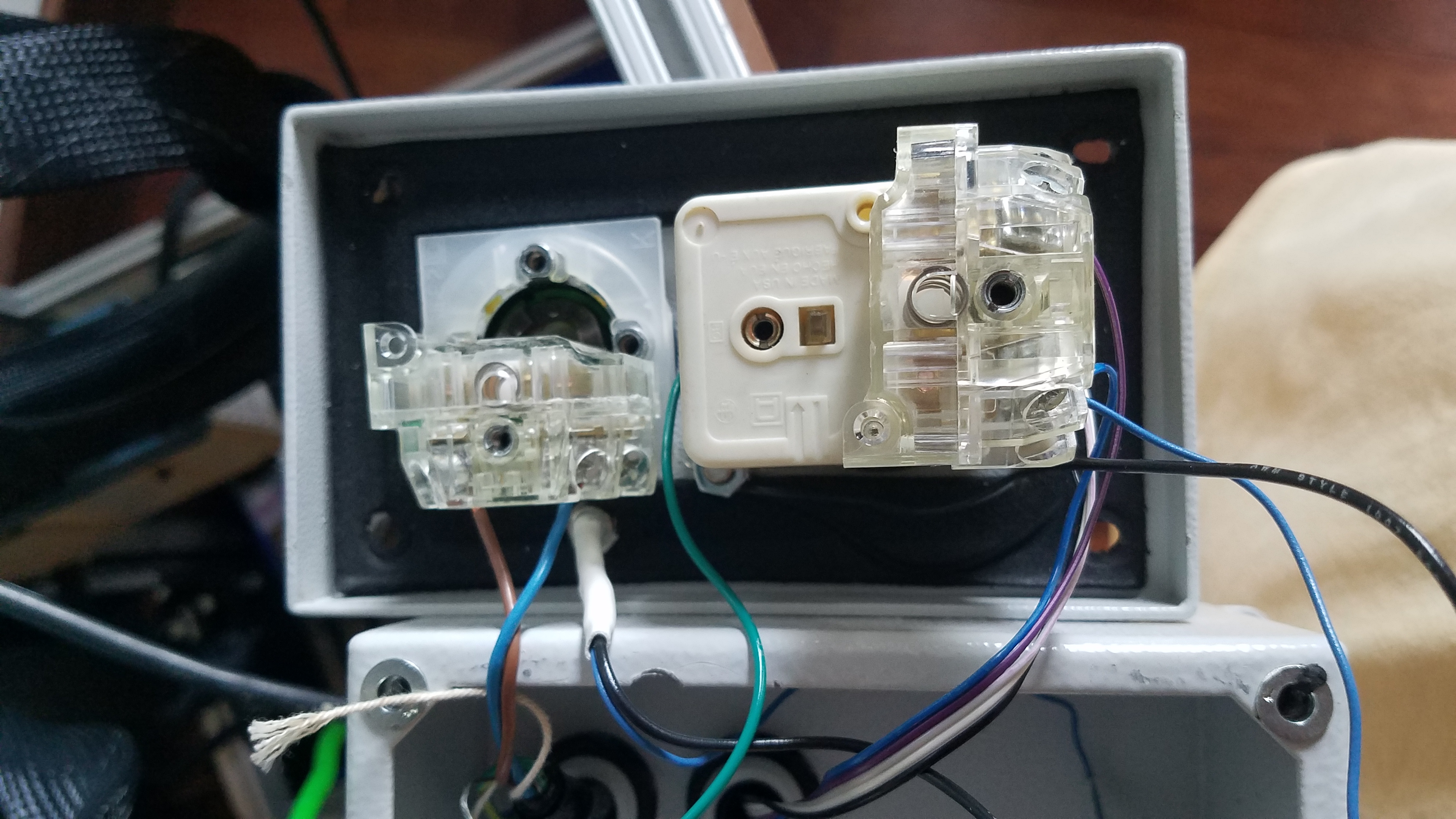
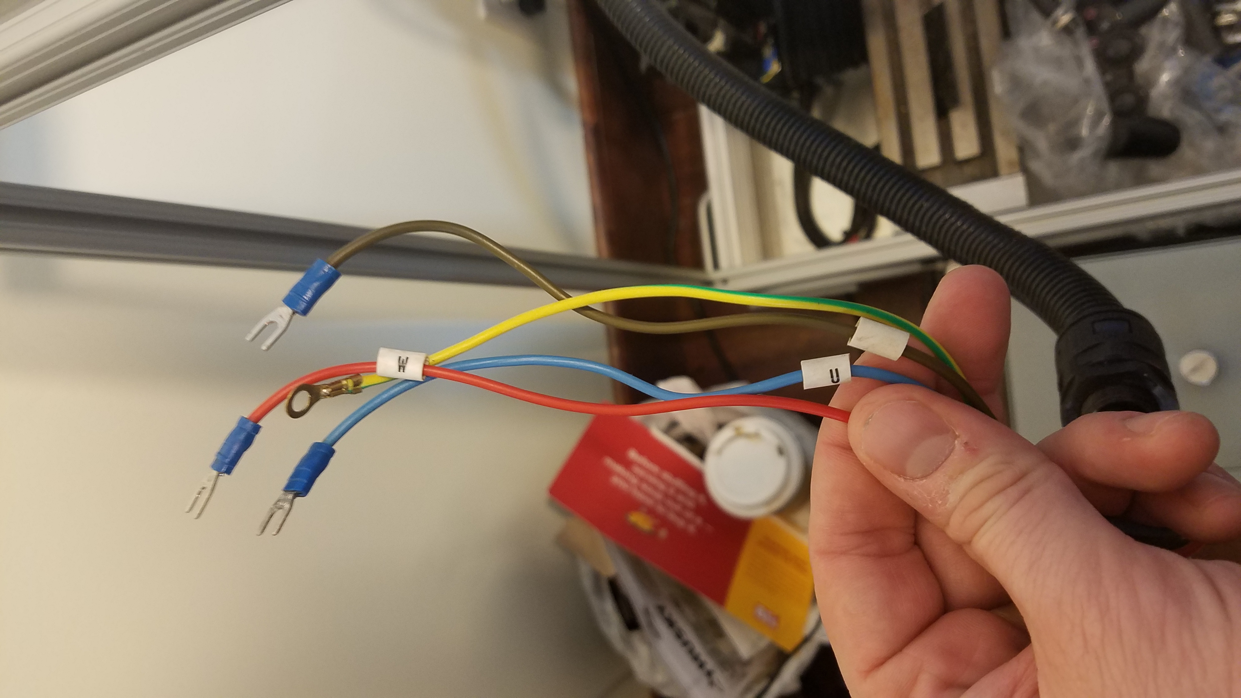
Power switch and E-Stop wiring in box.
The control electronics, end switches, and power supplies will be covered in other posts.